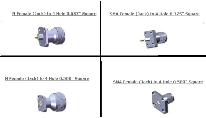
connector for 6-18GHz coax to waveguide(WRD650) adapter
im designing a coaxial to waveguide adapter in 6.5-18GHz and 500W power.
and im not familiar to connector types. i mean the dimension of inner pin and outer dielectric.
i design it in HFSS and the dimension of waveguide is about 20*7.5mm.
and the inside ridged high is about 2mm.
could any body help me in selecting a proper connector.
thank you all
You'll have serious difficulties to find a connector type supporting 18 GHz and 500 W at the same time.
E.g. high performance N connector series support 18 GHz, but only 200 W CW. Higher power 7/16 series isn't specified for the frequency range.
You can divide the 500W by 3 or 4, and then combine them at waveguide
Possibly, but phase matching is a bit difficult at 18 GHz. I would primarly ask about the design purpose. Do you actually have a RF source/load with the said parameters and coax interface? I guess, it's just an unrealistical homework problem.
In this case, you should use a 18 GHz capable N connector (e.g. Huber+Suhner) and mention the power limit.
main purpose of this design is feeding a horn antenna for max 200W power. but they ask if it could be designed for 500w power.
im agree with you, 500W is too high for 18GHz.
my problem is still exist. at low power(200W) CW what kind of N type connector can i use?
I want to excite the double ridged waveguide with a receptacle N type female jack. but i dont know what kind!(what are the inner outer diameter and dielectric length )
about the dielectric of connector, if it should go to the waveguide wall? if yes . how much.
i attach some kine of connector here.

and this is my HFss file. i use SMA for feeding. but i want to change t with N type.
Since return loss is a result of tolerance errors on ratios of dimensions that affect outer/inner ratio. This increases in sensitivity with smaller wavelengths, so smaller connectors require more precision to match.
High quality N type is the most common for this range.
well you are at the edge of what can be done. I suspect that a standard SMA connector can not be used because it will arc over at 500 watts.
so if you can prevent the arc over...it would probably handle it current wise (around 3.2 amps RMS). You need a Teflon sleeve over the entire connector length until it attaches to the ridge. if you have sharp edges near the interface, the E fields can be multiplied by a factor of 10X, so it would act like a voltage from the center conductor to wall of around 1.6 KV. zap!
there IS a special type N that works to 18 GHz, it has a reduced outer diameter so coaxial waveguide modes do not propagate.
well you say if i use a sharp tapper right under the connector , this improves the E field?!
where can i use sharp edge in waveguide? near connector or somewhere else?
if you can submit a picture please. thnx
You can buy SMA connectors rated for 500W peak, 2W average @18GHz , but temperature rise in the gold plating is also a limiting factor.
Bigger is better for thermal conduction when connector losses will be a factor.
I think you misunderstand. to handle 500 W, you DO NOT want any sharp edges.
like the double ridge waveguide, you need to machine a round on both edges of both ridges, or they might arc over to each other, or might arc over to the coaxial center conductor.
