Impedance matching and Output Power plot in ADS
时间:04-05
整理:3721RD
点击:
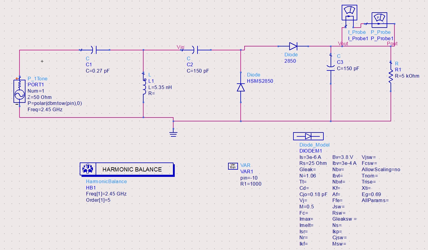
I am simulating a paper of 2.45 GHz rectenna using ADS. The circuit diagram given in paper and made by myself in ADS are shown below;
I wanted to ask the following:
1. Firstly, is my circuit correctly implemented?
2. How did impedance matching occurred via ADS matching tool? I mean what parameters were selected in the tool? i.e. load value, parallel load etc...
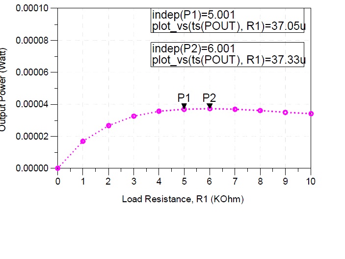
3. How to plot the output power vs R1 as shown in paper below;
PS. Reference paper attached.
Awaiting replies..
Regards


I wanted to ask the following:
1. Firstly, is my circuit correctly implemented?
2. How did impedance matching occurred via ADS matching tool? I mean what parameters were selected in the tool? i.e. load value, parallel load etc...
3. How to plot the output power vs R1 as shown in paper below;

PS. Reference paper attached.
Awaiting replies..
Regards
Read about parameter sweeps in the Circuit Simulation manual.
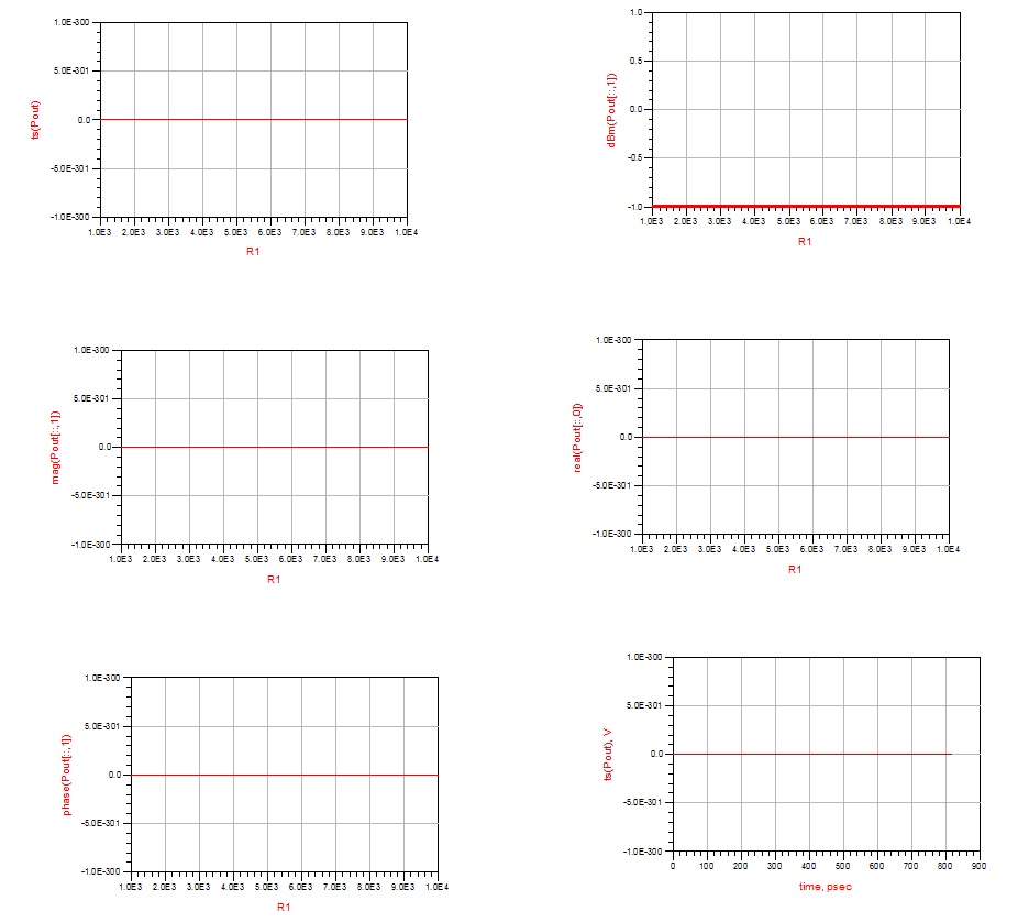
Well I am doing the sweep in the HB Simulator. I placed a Pout across C3 and R. But nothing comes up..Im getting following power...is it right?

