TE01 dielectric resonator coupled to perpendicular lines
时间:04-05
整理:3721RD
点击:
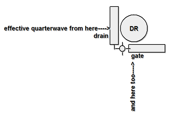
Recently i found parallel feedback DRO design where resonator is coupled to perpendicular microstrip lines. Usually parallel feedback DRO feedback lines are parallel.
In this design lines are perpendicular:
Both open lines after resonator coupling have effective lengths equal to quarterwave open stub. Then I tried to calculate feedback loop using known parameters, such as substrate Er, thickness, NEC transistor's S21 phase in available files had exact biasing as in PCB. But phase balance is not satisfied. Assuming that dielectric resonator phase shift is 180deg. It seems that with perpendicular coupling lines phase shift of DR would be 270deg, so in phase balance formula i must put additional 90deg?
Why there is 180 deg phase shift in TE01 dielectric resonator? Is it phase shift of dielectric resonator or relative phase shift for coupled microstrip lines, and comes only from H-field distribution? I mean h-field is clockwise for right microstrip and counterclockwise to left microstrip. If it is true, then for perpendicular lines there can be phase shift of 0deg.
In this design lines are perpendicular:
Both open lines after resonator coupling have effective lengths equal to quarterwave open stub. Then I tried to calculate feedback loop using known parameters, such as substrate Er, thickness, NEC transistor's S21 phase in available files had exact biasing as in PCB. But phase balance is not satisfied. Assuming that dielectric resonator phase shift is 180deg. It seems that with perpendicular coupling lines phase shift of DR would be 270deg, so in phase balance formula i must put additional 90deg?
Why? Isn't TE01 field rotationally symmetric? Or do you refer to transmission line delay?
in old book i found formula for dielectric resonator phase shift when it coupled to two parallel microstrip lines. Something with arctg(Q...). And for high Q it gives Pi/2. The problem author do not mention resonator type. And i did not found any other formulas for reaonator electrical length.
TE01 dielectric resonator have symmetrical H-field.
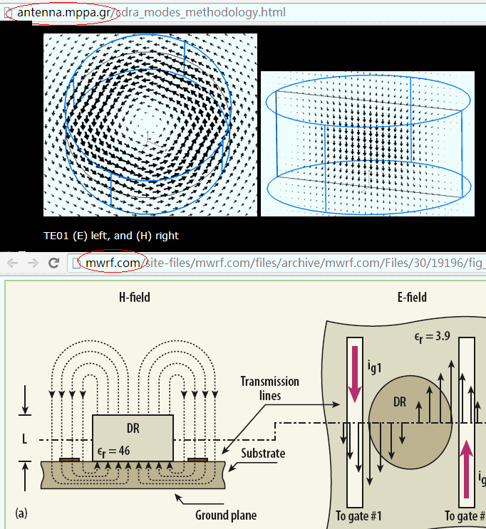
Why there is 180 deg phase shift in TE01 dielectric resonator? Is it phase shift of dielectric resonator or relative phase shift for coupled microstrip lines, and comes only from H-field distribution? I mean h-field is clockwise for right microstrip and counterclockwise to left microstrip. If it is true, then for perpendicular lines there can be phase shift of 0deg.