cross coupled lc oscillator
Sometimes it helps to place low-ohm resistors in series with capacitors, diodes, inductors.
Also high-ohm resistors across capacitors, diodes, inductors.
Try to reduce quantity of transistors/mosfets. Use simple analog switches if possible.
Varactors can be trouble in term of model.Using equivalent circuit instead of its model may help.
Where an inductor gets turned off abruptly, it may generate a high voltage spike. This might be a problem for the simulator. Therefore place a catch diode across the inductor.
I know what is ur problem its not about loop gain.
U have to apply a noise to circuit in order to make it work.
Try initial conditions set one of ur outputs to Vdd+0.1, it will work definitely.
Show me schematic and settings of ADS.
Do you use OscProbe ?
Do you use Transient Assited HB Analysis ?
Wrong.
If capacitor of LC resonator in VCO is increased, it requires more large negative impedance which is equivalent to large gm to start oscillation while osc frequency will be low.
Wrong.
See http://www.designers-guide.org/Forum...1234428781/1#1
It is not wrong. Of course I know that we should be sure about loop gain and negative resistance. You think that I simulate a VCO by choosing random values ?
I am quite sure that It wont work again. You can try it.
For transient simulation u need to apply IC, otherwise it does not work. I have simulated lots of them and I can provide you with one of them in ADS.
cheers,
simple cross coupled design using varactor with constant voltage.

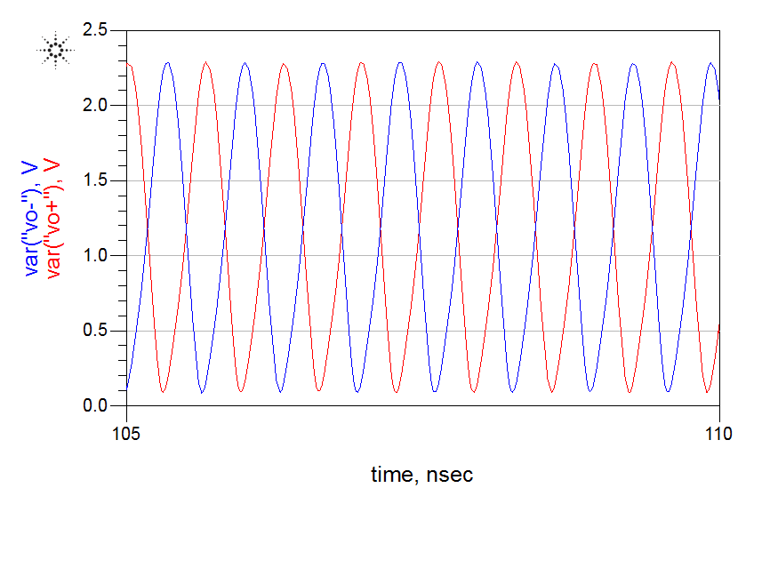
here it works in 1.43GHz
IC used here with Vo+(0) = 1.21v
VDD = 1.2
Tech = umc 130nm
If your VCO can be simulated in transient analysis, you can also use TAHB ( Transient Assisted Harmonic Balance ) option in ADS setup.
ADS will take this presumed initial result to apply into HB simulation.In this case , HB will probably converge.
No.
You can not understand plevrakis's situation.
Your opinion is correct for oscillator using Transient Analysis.
See https://www.edaboard.com/thread354854.html#3
However, he uses HB analysis.
Transient Analysis does not give such message.
His LC oscillator simulation can converge when not adding varactor.
However it fails when adding varactor.
Ok if this is the case. Why he wants to use HB simulation for VCO ?
you want to see output tones ? you can use fft.
(1) To get true steady state solution
(2) It is easy to get osc frequency at true steady state
(3) To get phase noise
we can also get phase noise and oscillation frequency from output fft.
Wrong.
You can never get phase noise if you use transient analysis.
i do tran and then get fft of output ?
Can you understand phase noise ?
We can never evaluate phase noise since Conventional Transient Analysis is a noiseless simulation.
We have to evaluate phase noise at low offset frequency.
So it is almost impossible, even if you use Transient Noise Analysis.
Solution of Transient Analysis is not true steady state one.
Resolution of osc frequency from transient analysis is bad.
It is common and advantageous to invoke HB Analysis for LC Oscillator regarding various characterizing as oscillator.
thats right :) tnx for explanation.
do u have any tutorial for ADS ? I mean HB simulation in ADS for CC osc ?
There is an OscPort, but i dont know where should I put it.
Typically, the probe is inserted between the resonator and the effective negative resistance. so where should it be exactly ?
well, I did actually. It seems fine.

http://www.odyseus.nildram.co.uk/RFI...Oscillator.pdf
However this is for very very old ADS.
See the followings.
http://www.designers-guide.org/Forum...1191085521/1#1
http://www.designers-guide.org/Forum...1191085521/3#3
coupled lc oscillator 相关文章:
- design and simulation of cross-coupled VCO using keysight ADS
- [moved] Fully Cross-Coupled Rectifier Configuration in Terms of Transistor Terminals
- Microstrip coupled lines
- Infineon BGT24MTR11 mmic: should RF in/outs be decoupled from ground?
- Coupled line filter design
- Unwanted DC voltage induced on a varactor coupled to DR? (dielectric resonator 10GHz)