Effect of metal resistivity on the characteristic impedance of microstrip line
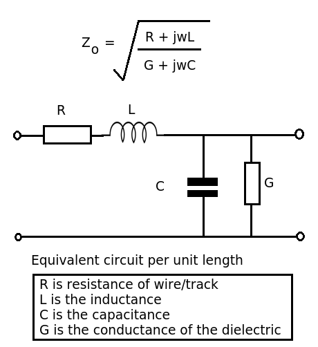
We know that the characteristic impedance of a microstrip line is given as follows:

In general the metal resistivity is so small that Z0 can be taken as sqrt(L/C). But if the metal resisitivity is not that small? Then according to the equation, this resistivity should affect the Z0. Is it true?
I did simple Agilent Genesys simulations of microstrip lines to see the effect of the metal resistivity on Z0 but surprisingly it didn't affect Z0. When I increase the metal resistivity, it only increases the attenuation. Any idea and help is appreciated.
The equation is correct. There's also an equation for transmission line loss, but you have omitted it.
It's true that conductor resistance (as well as substrate conductivity) affect in a first order losses. It also changes the characteristic impedance to a certain amount, unfortunately frequency dependent. Means if the resistance is so high that it affects the impedance, you are far from ideal transmission line behavior. You better avoid this operation region.
1st-order and 2nd-order approximations.
Are you sure the microstrip you used supports the RLGC model ? I think the resistivity parameter is only used to calculate the losses. It could be possible that specific RLGC microstrip models are available in Genesys.
resistivity metal Effect 相关文章:
- Metal patterns in PCBs
- ERROR 21: The metallic edge for the excitation does not exist (error in CADFEKO)
- modeling a metal plate with a conductivity
- Metals touching, produce EM waves
- Effect of number of fingers and width of a transistor on Efficiency and power gain
- What is the effect of power match on S11 and S22 in a PA
