Wilkinson Divider Isolation off-centered
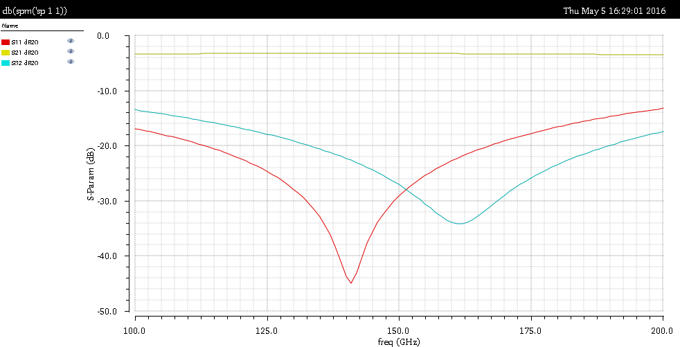
I am designing a Wilkinson power divider/combiner and I am getting an off-centered matching/isolation behaviour. Phase plots show that the divider gets an effective 180° phase shift between port 2 and 3 at around 160 GHz.

Any ideas about what could be the main reason for this shift and how to improve the isolation matching?
I can't imagine how Wilkinson power divider looks at 160GHz, is it PCB substrate or integrated circuit layout?
I read that rat-race can be used as power divider, do not remember about isolation.
s11 and s32 minima will of course occur at the designed center frequency for an ideal Wilkinson divider. That is obvious by looking at it's transfer function as well as the equivalent circuit.
But there are many ways how a 150 GHz power divider might behave non-ideal. To start with a simple point, it's about to impossible to implement a lumped resistor and keep both output lines separated at the same time. Also what about the transmission line ideality in your design?
Presuming it's just a simulation rather than a real device measurement, everything is under your fingertips. Just need to analyze the simulation results completely. They should show why.
It is an integrated circuit design and it looks quite similar to a typical PCB based divider. The transmission lines used for it are non-ideal of course, they have very low losses and exhibit quite a constant characteristic impedance over the whole 100-200 GHz freq. range.
I've just gave a look to the port impedances of each device and I guess I figured out why is it. Due to the non-ideality of the t-lines, they exhibit some spurious (very very small, but anyway it is present) capacitive part in the characteristic impedance. This makes that the resonance peak to shift toward the frequency point where this insignificant capacitance is out-resonated so I have technically to "rematch" the input impedance of the ports in order to get it perfectly centered or live with that.
I've just simulated the component within my system and I guess I will go for the second one :)
Thanks for the feedback guys,
BR
The S32 response depends on how well the isolation resistor mimics the zero length ideal. You can bring the S32 down in frequency by adding some parallel capacitance across the isolation resistor albeit at some loss of the maximum isolation.
