How to desing 2 way divider ?
I want to desing a 2 way divider with using coaxiel cable. Divider should work in 9-10 MHz. I am using AWR. But i have a lot of problems. I can't meet project requirements.
and i should not use wilkinson divider.
Can someone who is knowledgeable about this subject reach?
I'm adding my work below.
thanks.
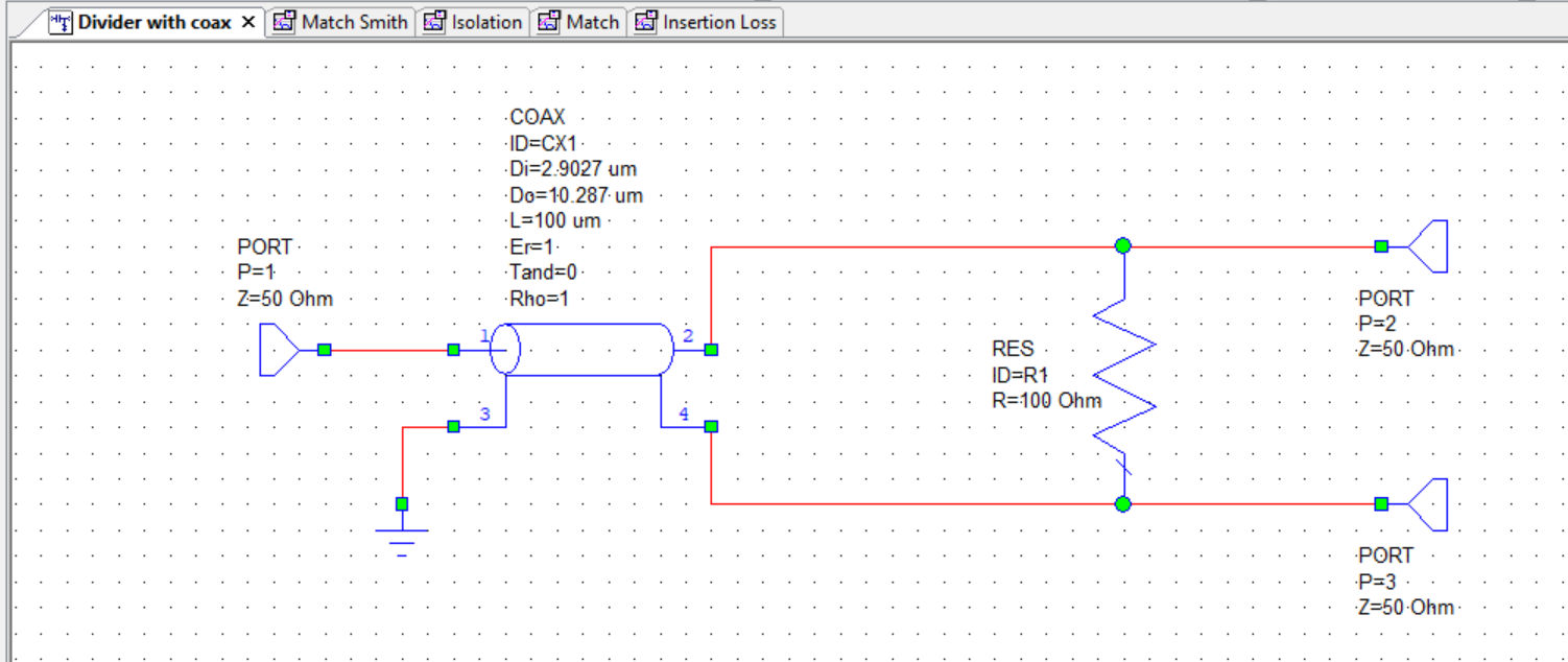
Doesn't work this way. With an ideal transmission line model (infinite common mode impedance), the circuit would work as a phase splitter. But infinite or reasonable high common mode impedance isn't feasible unless you place a ferrite core (transmission line transformer).
L=100um suggests you want to implement the transmission line on-chip. But at 10 MHz, it's like zero electrical length.
In terms of circuit modelling, you need to add a second transmission line instance that represents the common mode (coax sheet) impedance.
At 10 MHz, Power Dividers with Transmission Line are not practical.
Instead, Ferrite Transformer Based Dividers should be considered.
thanks for your reply.
I'm not sure if I should use coaxiel. What do I need to do to use a ferrite core?
What's exactly the intended function? Two way 50 ohm -3dB 0° power divider, similar to Wilkinson operation?
What are the constraints? How far it's required or wanted to use transmission lines? Post #1 suggests an exercise problem, e.g. using λ/4 transmission line. Although a bit lengthy, it could be still implemented at 10 MHz.
thanks.
12 watt- 50 ohm input
6 watt - 50 ohm 2 output, 0° - -3dB
this is my purpose.
I should not wilkinson divider. Because λ/4 line length not suitable for project. The cable lengthens too much. ( our operating frequency is 9-10 MHz )
https://www.mwrf.com/technologies/pa...power-dividers
thanks for your reply. I'm looking at this post.
Wilkinson structure can also be considered being as Lumped LC elements.If the bandwidth is not too large, appropriate LC elements ( high voltage and current capable types ) may serve low loss divider.
I notice that the transmission line transformer circuit in the post #7 link has errors. Also it's not mentioned that it implements 2.25:1 rather than 2:1 impedance ratio.
Hello BigBoss, isn't a power a bit high to do this with lumped structures? I'm not sure there are parts with those power ratings, what's your opinion on that?
How kW Range RF Power is Carried ?
Yeah, there are many High Power RF Lumped Components.
https://johansondielectrics.com/surface-mount-products