Re: (Mixer design) IFp and IFn have same phase
All the transistors work in saturation region. I also tried to increase the VDD to enlarge the Vds margin of transistors. The problem still happens.
So, the problem may be 10nF caps? In the tutorial, 10nF caps were used. How much the block caps value I should use?
No it is not about dc caps. But here ur problem is not feedthrough actually. It seems so wierd. Try only single RF input mixer to see if it gives the same answer or not.
Sorry if wasn't clear enough.
I see that in Cadence RF manual that the balun is specified with 50 ohm output impedance. So the common mode impedance isn't particularly high, but higher than the ideal LO voltage source.
In any case, the feedthrough is present. I'm not sure if the 2nd harmonics is mainly generated by MN0-MN3 transfer curve non-linearity or non-linear Cgs, in case of doubt both. Please consider that the 2nd harmonics of LOp and LOn are in phase, so they aren't cancelled by the symmetrical mixer topology.
Unfortunately the 2nd harmonic generated by transfer curve non-linearity will be send to the output even if the RF input is perfectly blocked.
It makes sense to watch the output through a low-pass filter which suppresses LO harmonics.
I think out friend does not understand the words you use like common mode impedance and mn0-mn3 and etc. you have to explain in a simple way.
I dont think so feedthrough makes this 0 deg phase problem. There should be a major fault some where.
Try to remove baluns and do simple simlations like using Rl at the output or simulation without baluns.
what kind of balun are you using in cadence ?
Hi FvM and Ata_sa16
Thank for keep helping me.
I return to single balance mixer:
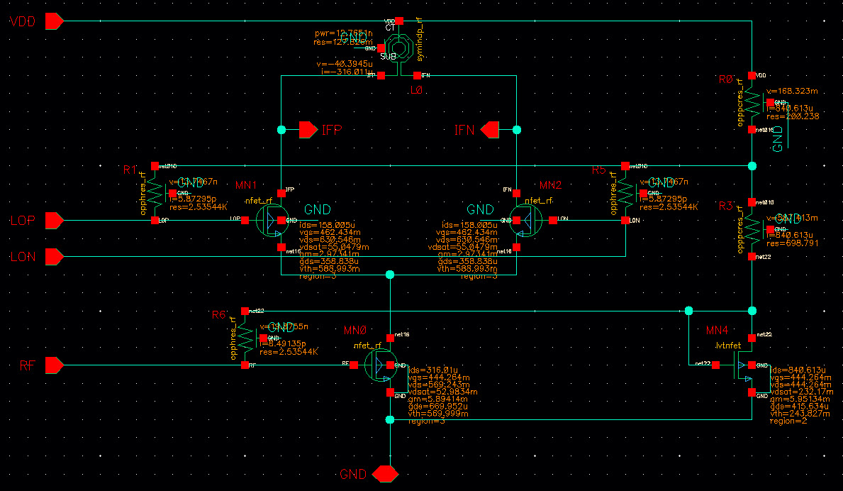
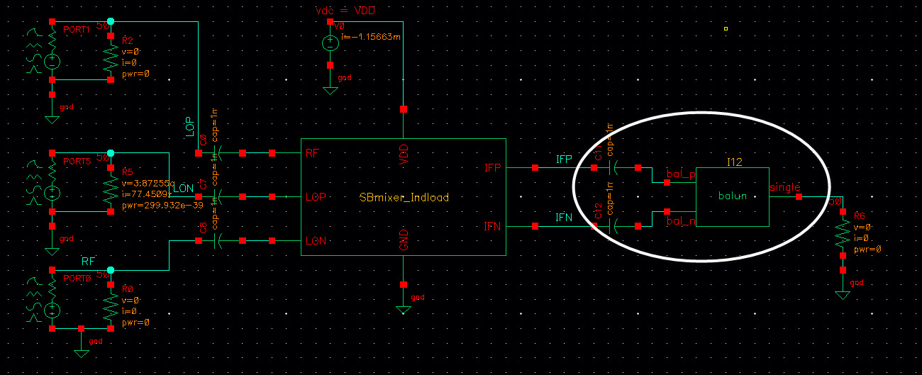
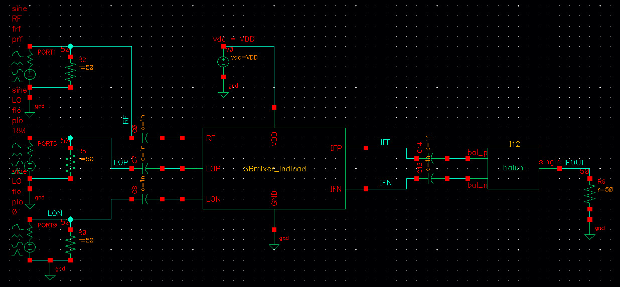
schematic
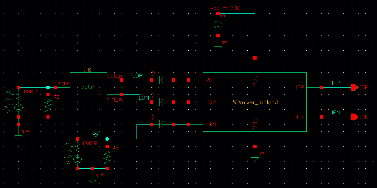
1 testbench WITHOUT balun

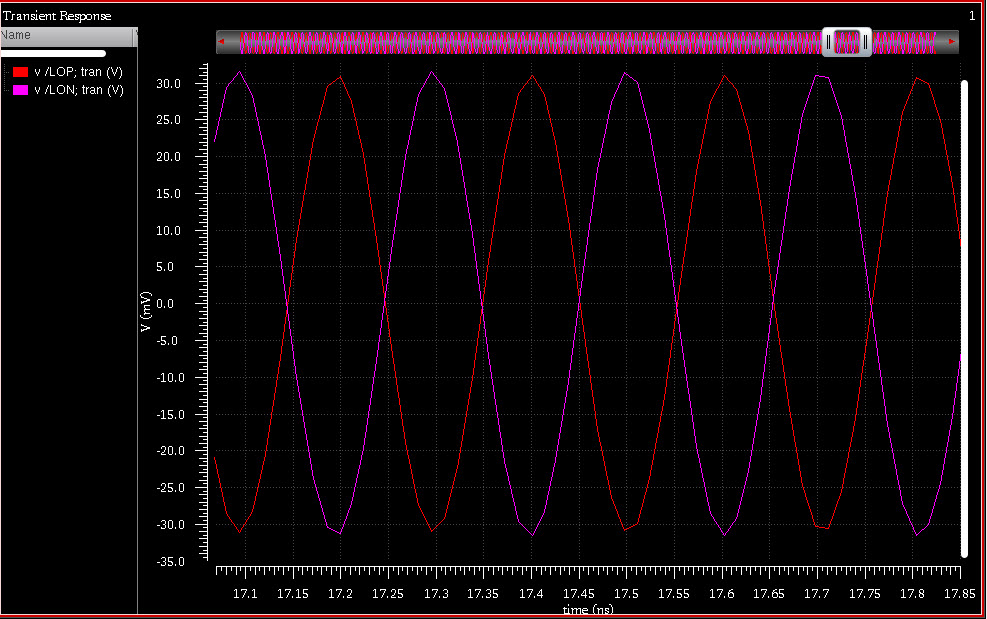
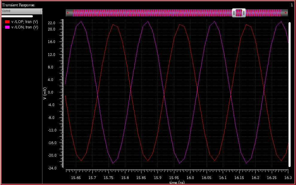
LO signal
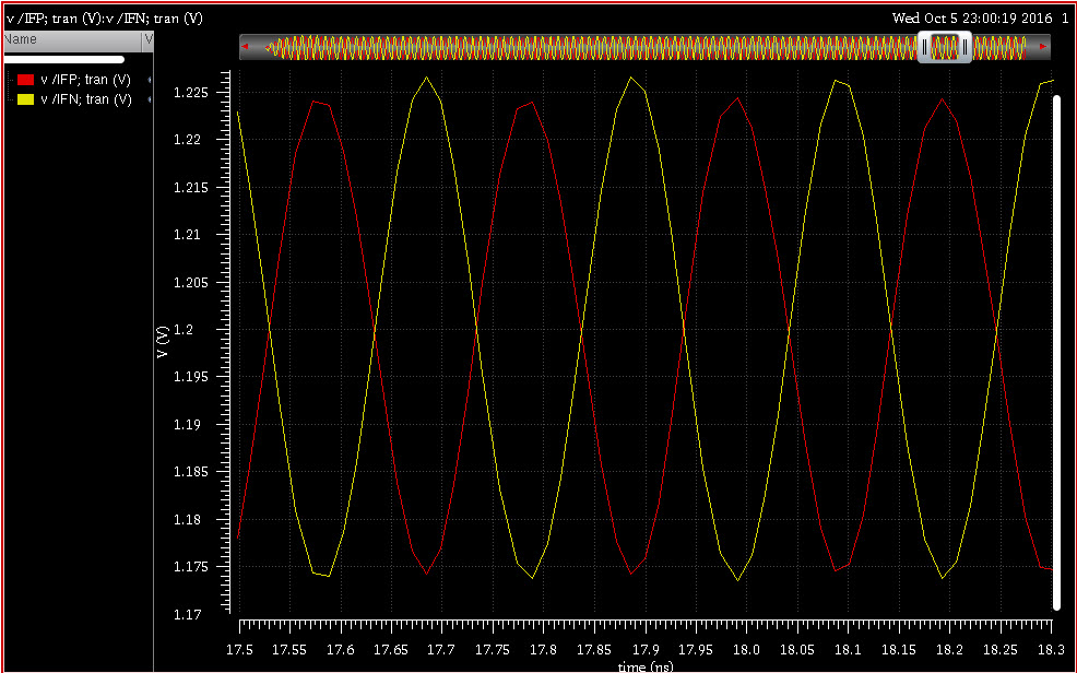
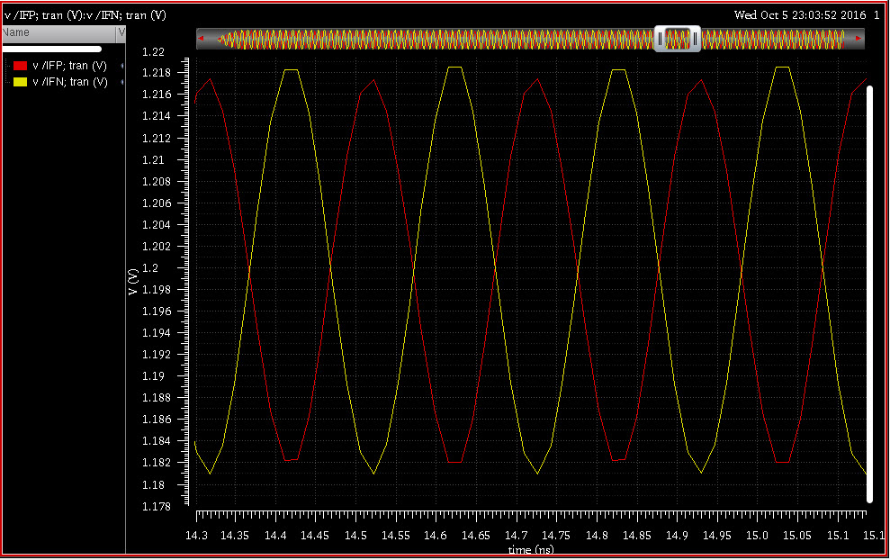
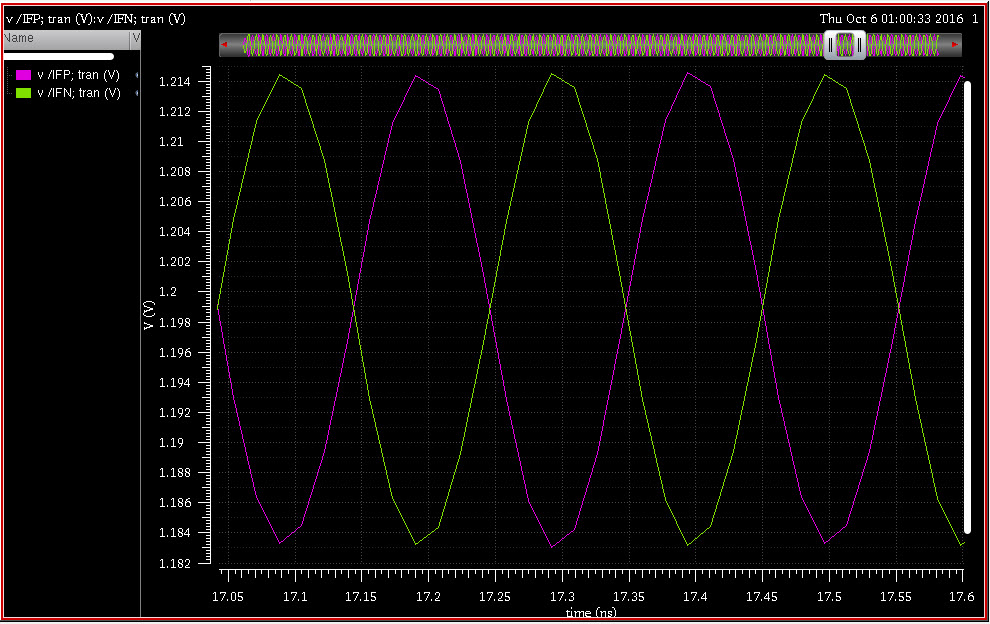
IF signal
2 testbench WITH balun (i am using balun in rflib of cadence)
LO signal
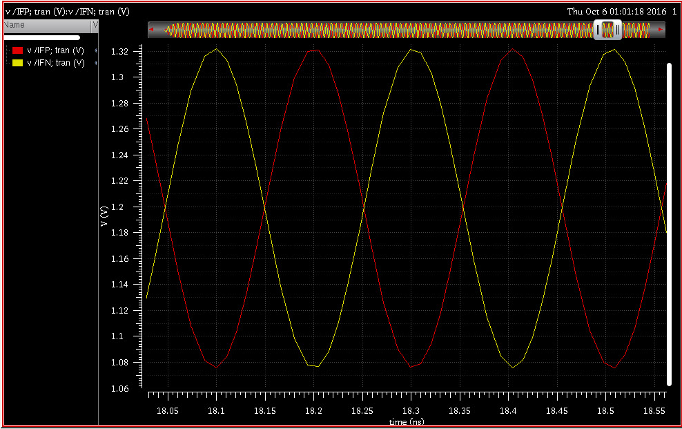
IF signal
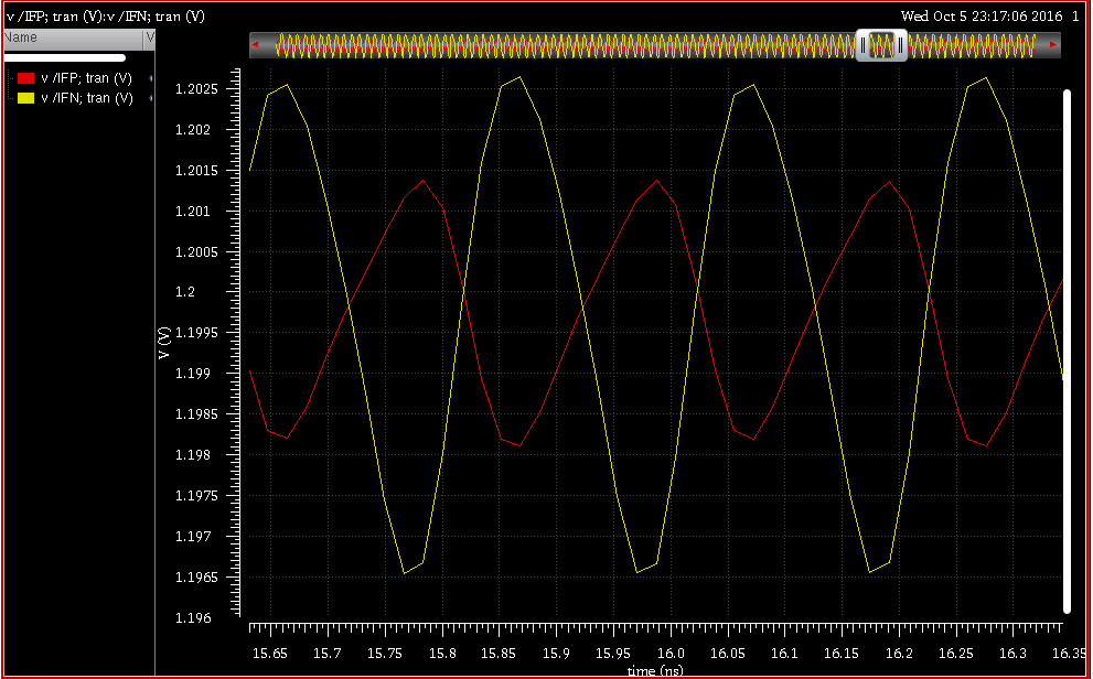
3. If i use balun at IF output, IFP and IFN are not equal!
I suggest to generate a fourier transform of the output signal (both single and differential ended) to better understand which signal components are actually present.
You should also increase the timing resolution of transient analysis for a cleaner output signal.
You can possibly optimize the ratio of wanted output signal to unwanted mixer products by reducing the LO drive level.
Thank FvM,
The problem is I made wrong connections. I know I am so stupid. I am sorry because I wasted your time.
Anw, now balun may not be the problem (it slightly affects to the magnitude of IF signals). The below screenshots are the IF signals with and without balun.
Testbench
IF with balun
IF without balun
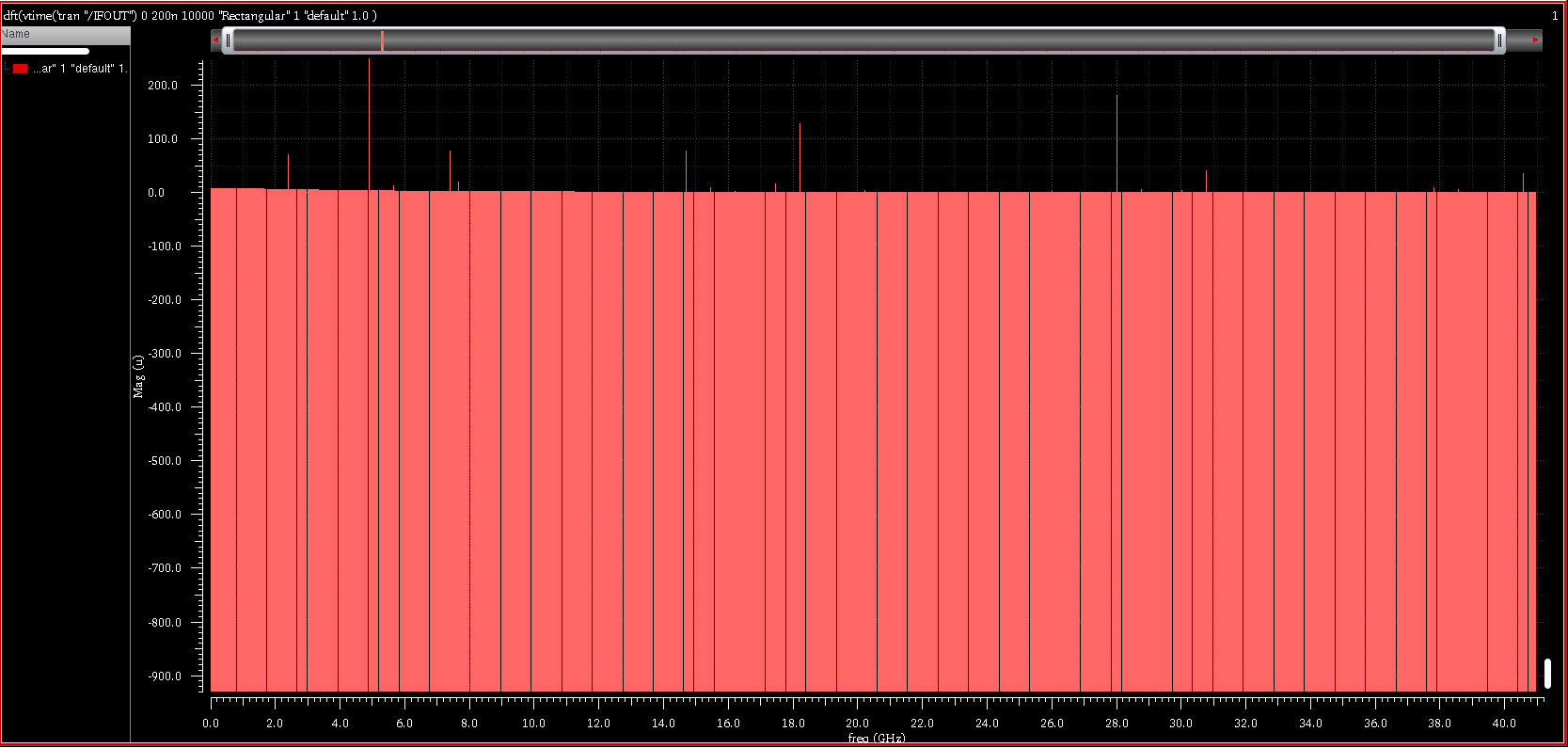
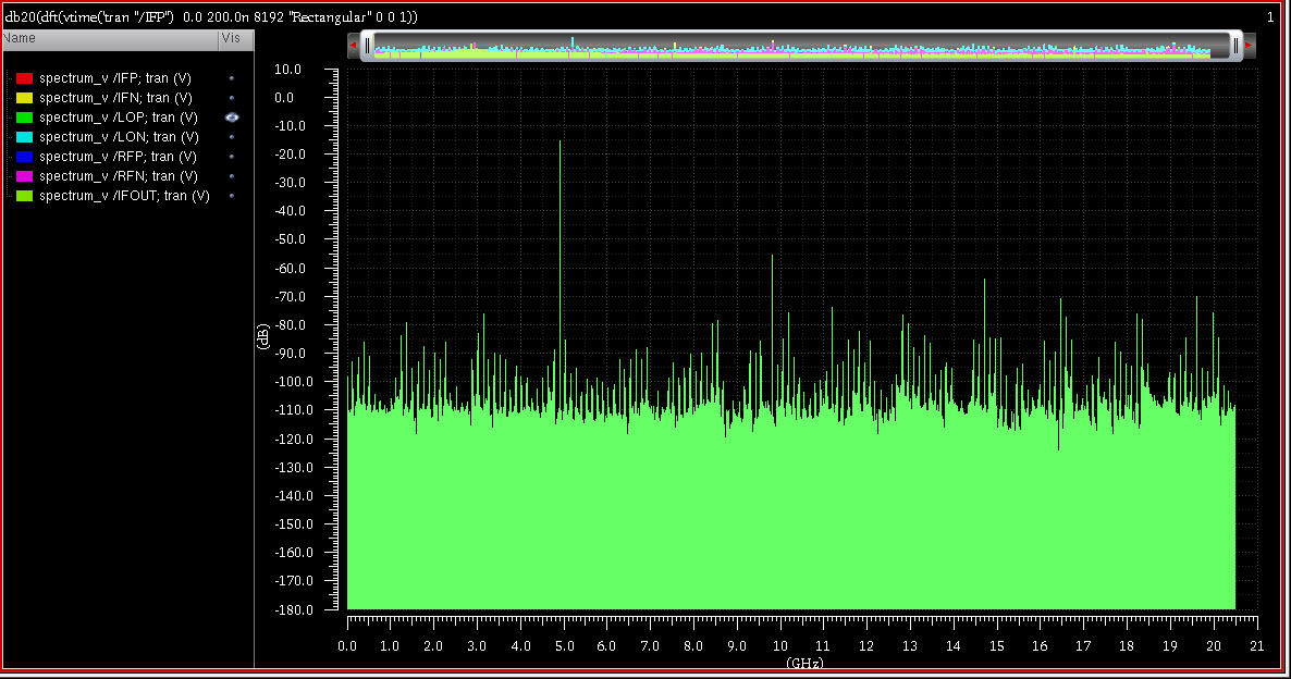
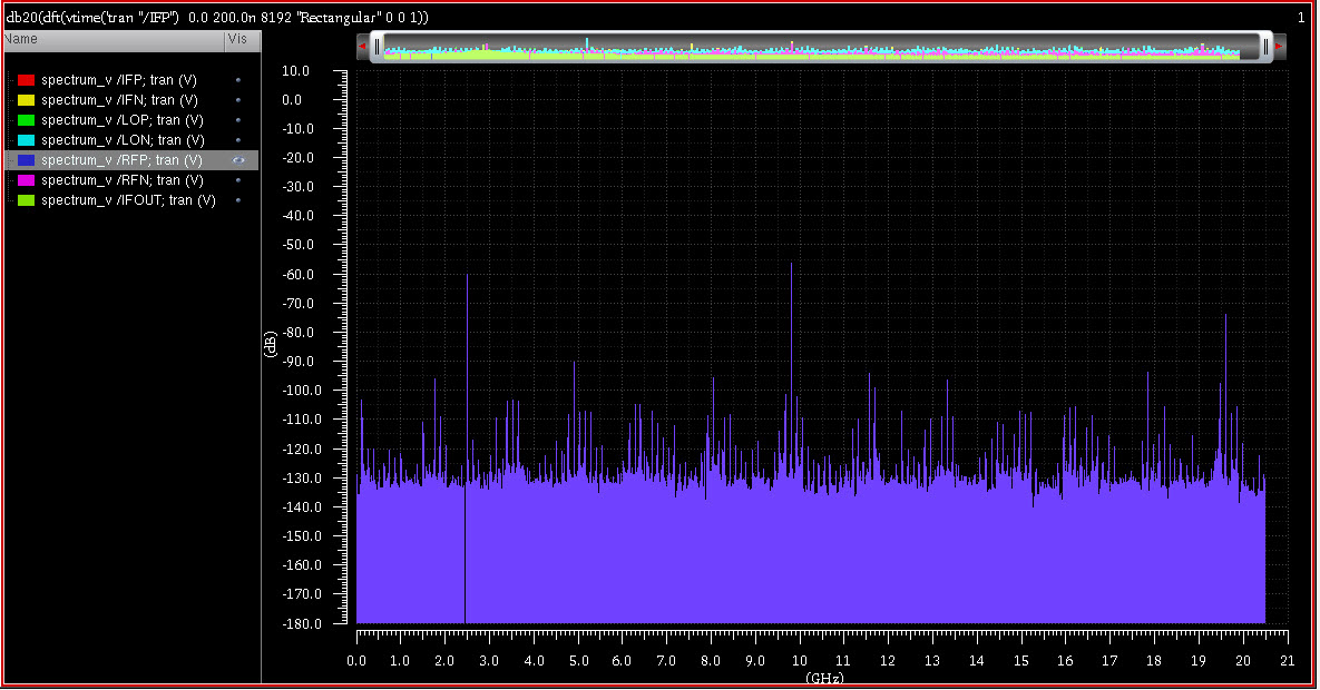
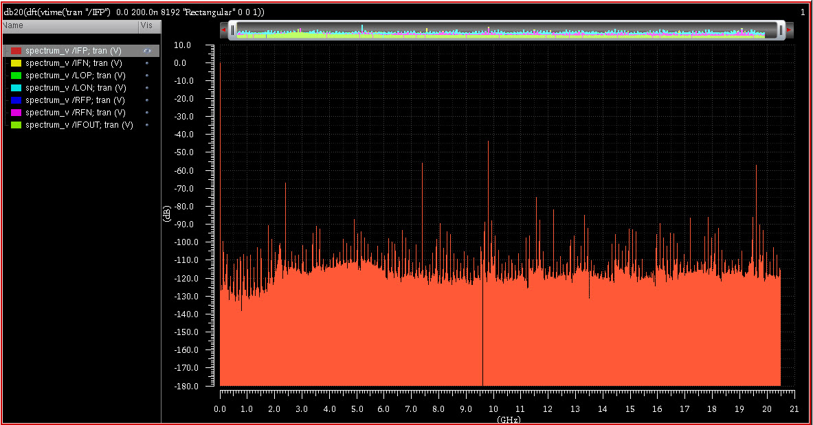
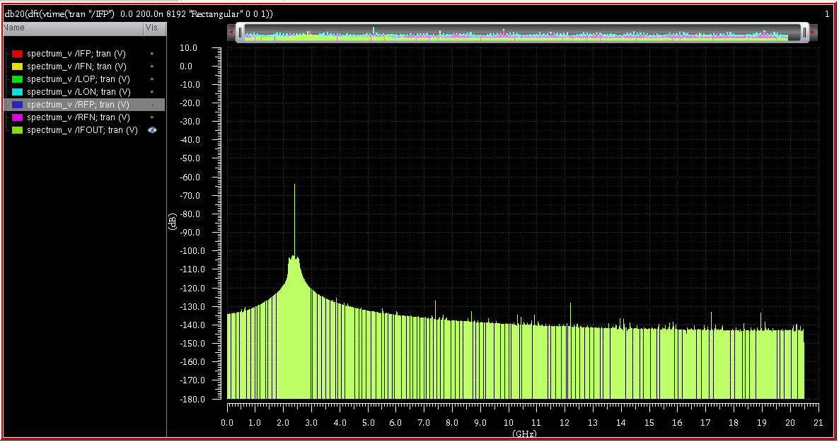
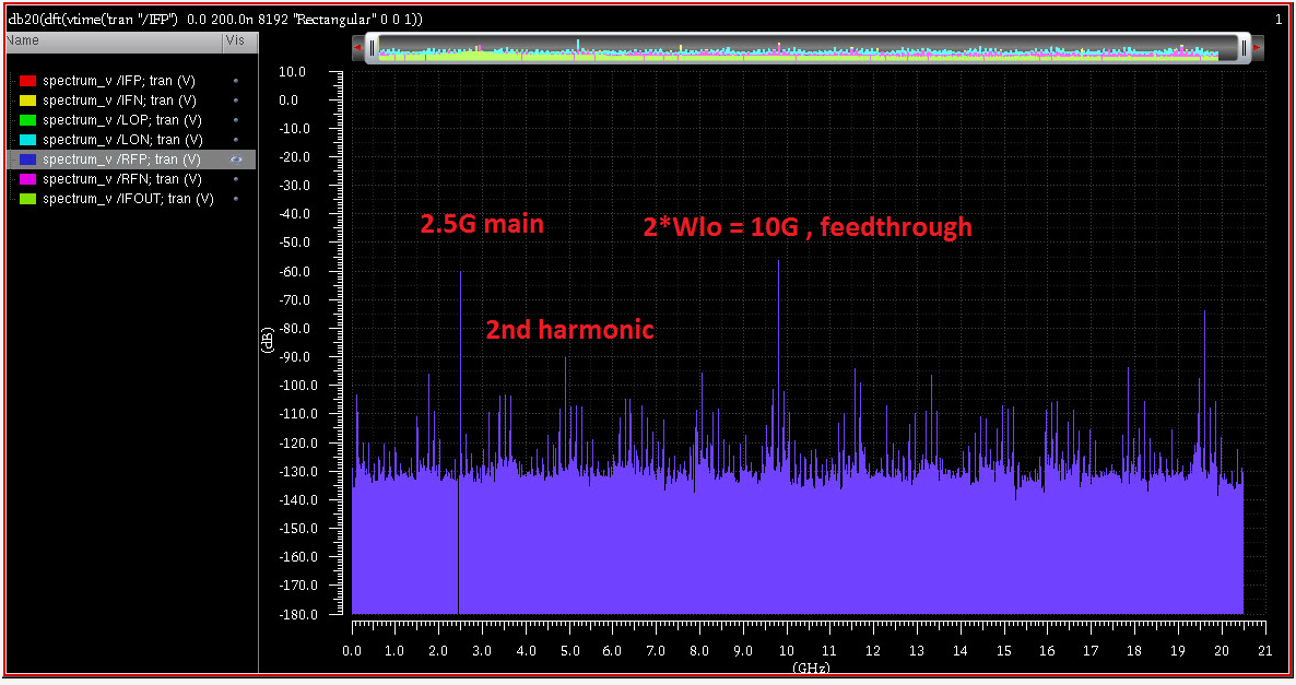
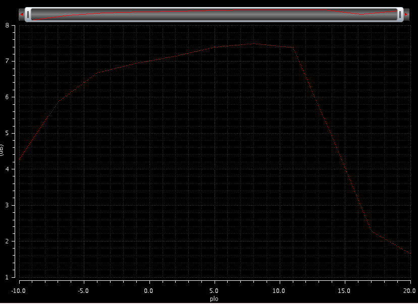
However, this is the dft analysis at IFOUT node. Except LO signal at 4.9 GHz, there are many harmonic which larger than IF fundamental! Did I made sth wrong
LoooooooooooL
I told u didnt I ?
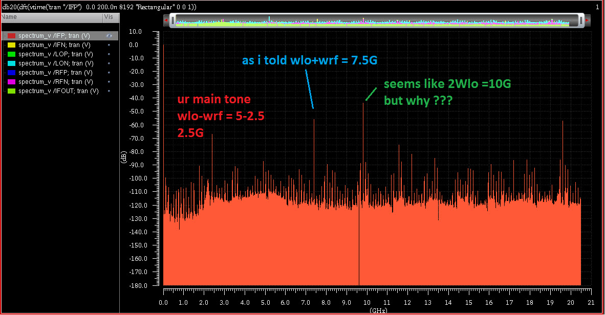
you will have two tones at the output
Wrf-Wlo and Wrf+Wlo
and also your system has non-linearity so it may contain another tones.
Try to put a low-pass filter to get the main frequency.
I am going to design Gilbert cell mixer. There are many harmonic in the design
LO signal
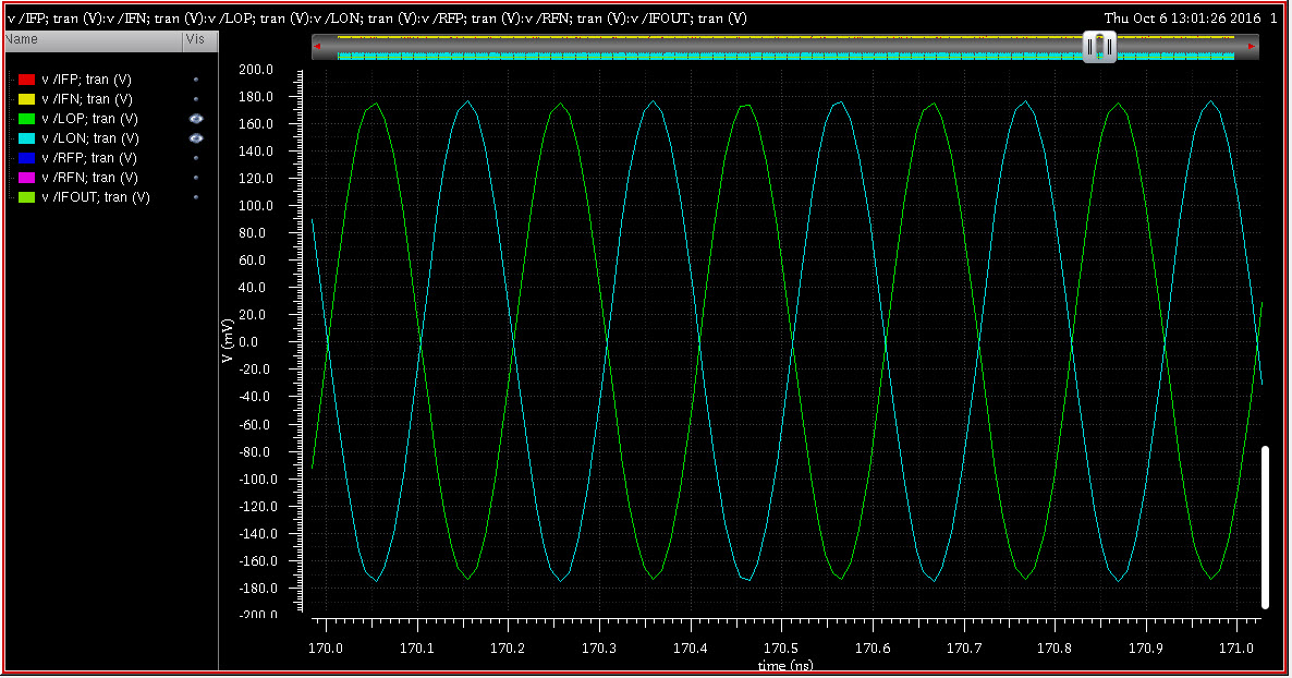
RF signal
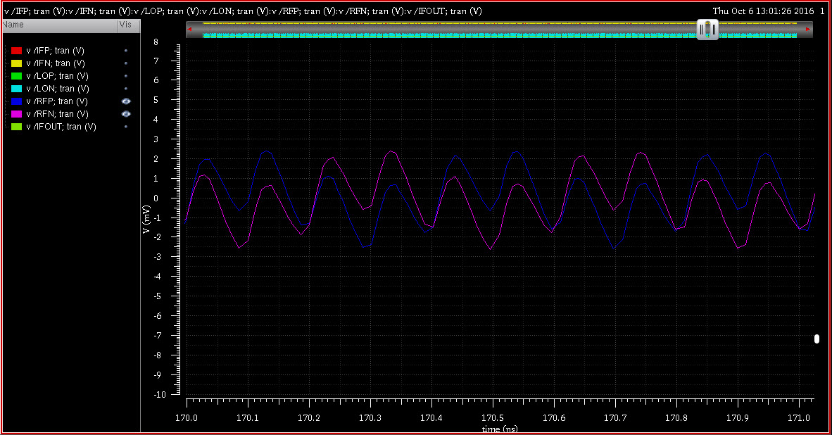
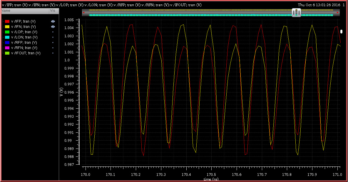
IFP signal
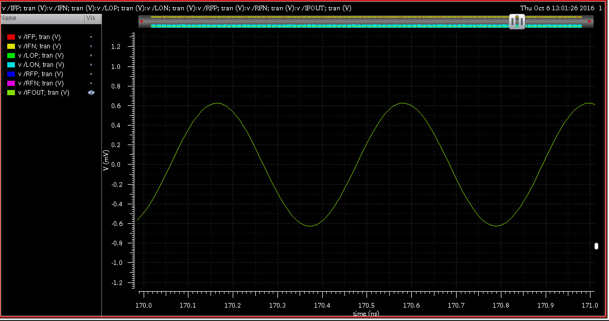
After the balun and fiter, I got the final IF output
I don't want to use filter so I want to design double balance mixer. Can I do sth to improve the performance?
There are probably three sources of non-linearity in your results
- inherent limitations of the low voltage design
- effects of non-optimal design parameters (transistor areas, bias, signal levels)
- simulation artefacts by insufficient time resolution in transient analysis
we can say:
Honestly I don't know the reason. Do you think the low power design (low Vds transistors) cause this problem? I am trying to simulate with different supply voltage, I hope to see sth.
Increase the Vds margin does not help. So, my question is how to choose the transistors' size?
Show me your IFout after balun without LP filer.
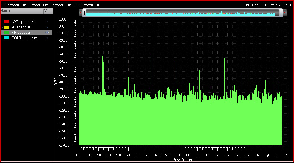
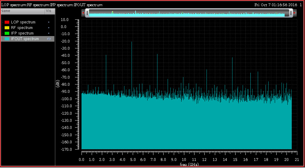
The following screenshots show the simulation without low pass filter.
IFP (before balun)
IFout (after balun)
Ata_sa16, you helped me too much. I think my question is now so far. I should read more articles. Btw, if you know good papers about mixer, please recommend to me. There are too much for beginner like me. I would like to thank again for your help.
ktx2222
can you show me how you take fft in cadence ? I forgot !
I mean how you get the spectrums ?
I found your mistake !
tell me what is the value of your inductor ?!?!?!?!
I have also set up simulation but i get 0 phase like you ? which connection u made wrong ?
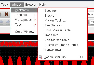
Click on the waveform you want to see the spectrum, then click Window => Assistants => Spectrum
I supply the VDD through 6nH inductor. I use 3 sources for my single balance mixer: RF, LOP and LON. I made mistake with RF and LOP, so IFP and IFN are totally different.
I think, IFP and IFN are in phase is ... normal. Because of high LO power. I am trying with double balance
imagine ur using 6nH inductor and u have cgd capacitance which is small lets say 100fF.
then your oscillation frequency is: 6.5 Ghz !
the problem is inductor ! when i use 500 ohm resistance as load it works
and also your IF signal should be in Mhz, i do not understand why you mix 5Ghz with 2.5Ghz ?
it should be 2.5Ghz with 2.4Ghz !