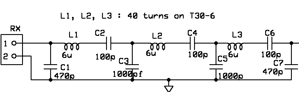
help calculation values for bandpass filter
You could use node analysis or loop analysis. Do you have a more specific question?
Well, you first have to know what the input and output impedances are. Since the filter is symetrical, the input and output impedance is the same.
As i understand that C1 and C7 are for the input/output impedences based on the frequency, but what about C3 and C5?
And how all the series 3 stages LC define the bandwidth of the filter? If they have the same value?
Thanks
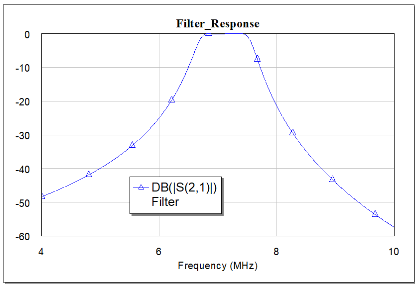
This is Band-Pass Filter approx. @7.1MHz Center Frequency.
how to analyze a circuit for RF? You could download a free version of Spice, or maybe Qucs, and just input the component values and analyze it.
The above comment about "impedance" is important though. Is it a 50 ohm generator and a 50 ohm load? Or is it a voltage source, and high impedance oscilloscope for a load? Makes a huge difference in the response.
https://www.microwaves101.com/encycl...e-eda-software
You can conclude that at least one port has a resistive termination, otherwise the filter gets resonances with infinite Q.
The filter topology is called coupled resonator, the shunt Cs are providing the coupling.
values calculation filter 相关文章:
- Automatic selection of element values of antennas impedance models
- How do I plot load pull contours using values from ADS plots (P1_Contours) in excel?
- How to know Proper Values for ZL and ZS , Load Pull and Source Pull in ADS
- How to check different temperature values for design of LNA IN ADS.
- AppCad Values Not Yielding Good Results for CPW
- help udrestanding the values in this table