SMA bad connection mismatch in PCB from 6.5 GHz (measurement and HFSS simulation)
时间:04-04
整理:3721RD
点击:
Hello,
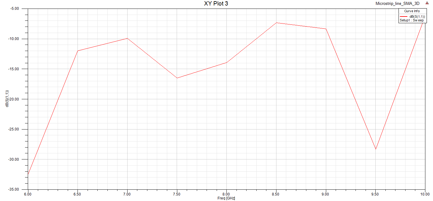
I simulate the SMA model in HFSS (a PCB board which comprises of 2 SMA connectors and a transmission line) and it shows the mismatch problem.
The mismatch does not come from the transmission line nor coaxial transmission in SMA (I verified it) so I suppose it comes from the connection between SMA and the board.
The SMA model is designed to simulate the SMA connector JOHNSON 142-0701-851 (RF / Coaxial Connector, SMA Coaxial) which works up to 18 GHz.
http://uk.farnell.com/johnson/142-07...ohm/dp/1019325
I found it is strange that I see the same mismatch in my measurement with this connector. So I wonder if my installation (as I show in the simulation) is not good ?
Should I choose another SMA connector ?
Thanks !
Here the hfss simulation :
SMA Test.zip
I simulate the SMA model in HFSS (a PCB board which comprises of 2 SMA connectors and a transmission line) and it shows the mismatch problem.
The mismatch does not come from the transmission line nor coaxial transmission in SMA (I verified it) so I suppose it comes from the connection between SMA and the board.
The SMA model is designed to simulate the SMA connector JOHNSON 142-0701-851 (RF / Coaxial Connector, SMA Coaxial) which works up to 18 GHz.
http://uk.farnell.com/johnson/142-07...ohm/dp/1019325
I found it is strange that I see the same mismatch in my measurement with this connector. So I wonder if my installation (as I show in the simulation) is not good ?
Should I choose another SMA connector ?
Thanks !
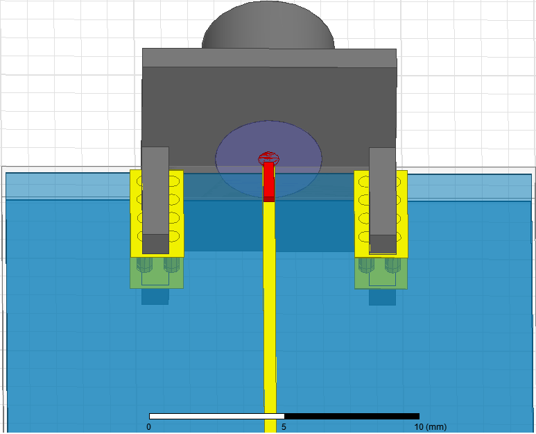

The SMA that you posted is designed for a 1.57 mm PCB thickness. Beware that its central pin width is 0.51 mm, and to get minimum of reflections, the thickness of the 50 ohms transmission line on the PCB should be the same.
I changed the central pin width to 0.38 mm to fit the transmission line, but this change does not affect a lot the matching.
I also think the transmission line should be a little bit bigger for solder.
The same result when I change the central pin width to 0.51 mm, and I change h substrate to 0.303 mm to have the transmission line width of 0.67 mm.
Here the hfss simulation :
SMA Test.zip
mismatch PCB connection 相关文章: