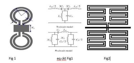
L-C loaded left handed metamaterial....equivalent circuit Cr Lr Cl Ll
hello....
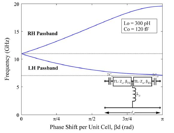
how to find the L and C parameter value of the TL and get this dispersion curve
Are you asking about L:C ratio? To a large extent it has to do with available current. Your neighboring resistances are also factors. Expect input resistance and output resistance to affect the rolloff curves.
If current is small then choose high L, low C.
If current is large then choose low L, high C.
thanku sir....
is there any formula to calculate values of L and C which represents right hand metamaterial..
can we design this circuit in ADS ?
1.
Your schematic appears to be symmetrical. It works as a high-pass filter. You should post a full schematic, if we are to discuss its response when input is applied at certain points and output is taken from certain points.
2.
Phase shift and amplitude change go hand-in-hand. Once you simulate (or calculate) the values which create a given rolloff curve, then you will also observe phase shifts in a corresponding amount. To watch how this happens, it is easier to start by examining behavior of one RC cell. Then one RL cell. Then go on to combine coils and capacitors.

yes sir....schematic is symmetrical.
I have attached one image file....please find attachment..
Here i have designed the metamaterial structure and got the S11 and S21 parameters....
and now as mentioned in the image, i am trying to get the lumped element values Lr, Cr, Ll and Cl...
Here lumped element values L0 and C0 for Left handed metamaterial is given and for the right handed charecteristic (Z0,Bl transmission line) is given.....
i am trying to get the values of L and C which equivalently produces transmission line characteristic.....and hence can get the dispersion curve for the same...
It is impossible to produce a left-handed metamaterial which is also non-dispersive. This is restricted by causality.
There are simple equations for designing such left-haded transmission-line metamaterials. See for example the (now) classic paper:
G. V. Eleftheriades, A. K. Iyer, and P. C. Kremer, "Planar negative refractive index media using periodically L-C loaded transmission lines," IEEE Trans. Microwave Theory Tech., vol. 50, no. 12, pp. 2702-2712, Dec. 2002.
thanks a lot sir....... for your valuable information....
Sir....
equivalent circuit for fig1 and fig2 are same?
if different .....what is the equivalent circuit for fig2.......image attached....
They look roughly equivalent to me, under some approximations.
Sir.....
what will be the exact equivalent circuit for the fig2