Microstrip Negative Resistance Oscillator Nyquist plot Encirclement issues
时间:04-04
整理:3721RD
点击:
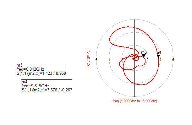
I did a basic common source negative resistance oscillator using source inductive feedback and achieved |Tin|>1.3. In the nyquist plot, (I checked s2p of CE3512K2 and the NE3210S01 nonlinear model, they are giving similar traces) I am getting two clockwise encirclement @6 and @9.68 GHz (as shown below)
But when I am doing OscPort analysis using HB setup, I am getting 6GHz oscillation with 9.5 dBm output power, but I cant see the 9.68GHz one even if I change the HB fundamental frequency from 6 to 10/12/16.... I get actually the third harmonic (17.56 GHz) as the fundamental frequency at the output but not the 9.68GHz one.
In papers, I havent seen such 2 encirclements. I perhaps did mistake(s). I followed the usual procedure but cant figure it out to get only one clockwise encirclement. I'm being hopeless, could you please give your comments on this?
This oscillator was fabricated and measured, but surprisingly, it only produced 9.68GHz in the spectrum analyzer without any trace of 6GHz signal. It might be the 2 encirclements in Nyquist plot
At a particular time, a transistor can oscillate only at one frequency, point where meets Barkhausen stability criterion.
Even this is a necessary condition, Barkhausen criterion is not sufficient. Some circuits satisfy the criterion but do not oscillate. Practically there is no simulation that guarantee 100% that a transistor will oscillate.
Resistance Oscillator Microstrip 相关文章: