Performing Coupling in resonators using (OrCad) PSPice
>>>We have,out of total, 5 main couplings
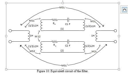
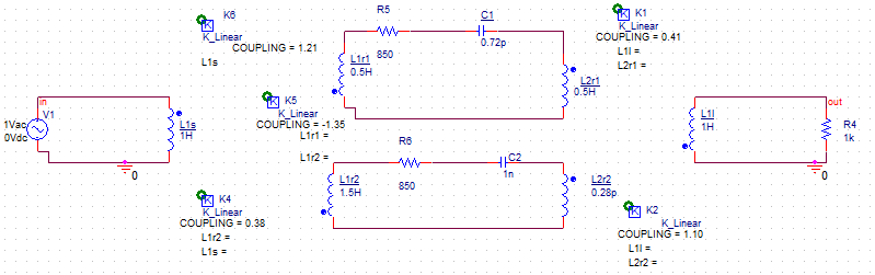
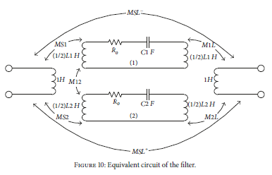
>>>The cicuit layout shows this.
>>>Analog R L C are used
Hoping for a positive response.
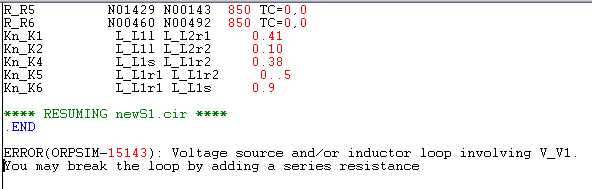
You defined wrongly the K_LINEAR instance.
This is how I would write it for "K1" for example:
k=0.41
L1=L1l
L2=L2r1
I use that as well and works great.
Review coupling of K2,K5 and K6.
Thank you for the reply..........
But I further need guidance, how to change the remaining couplings?
I have done this L1=L1l L2=L2r1 with the K1, (attachment), but how to change remaining K2-K6 with such expressions? Also check the property window pane of the schematic.. Is that correct?


I think this problem is solved...
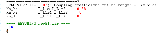
Now, this is creating trouble (attached) although alll coefficients are in range..
Spice parameter K isn't the same as mutual inductance M. Review the reference manual about there relation.
|K| > 1 is physically impossible.
I have worked with the K, and purposely make it <1, Now this new problem is there...
Keep in mind that with more than two windings, there constraints on the values of k aside from -1<k<1. For example, if you have three inductors L1 L2 L3, then if you define k12=1 then k13 and k23 must be equal to each other (k23=k13).
Rather than coupling coefficients, you may find it more intuitive to model your coupled inductors with an impedance matrix Z.
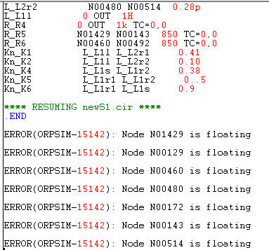
You need ground at every single circuit, unlike your post #1 schematic.
I don't know why the loop is to be broken, as mentioned in the err?
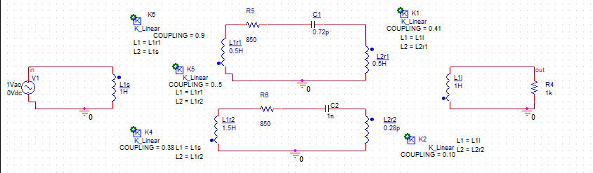
V1 is applied directly across L1s. Add a small series resistance.
Coupling of K5 is 0..5 ? Correct the double dots.
Thanks for the guidance.... its working..
Now, I want to done the couplings which are >1 in magnitude.. HOW can I make it possible?
Is the inductors supporting k>1 mag, are different than normally used?
I have used a discrete type inductor..
|K| > 1 is physically impossible. You have to denormalize the values of the coupling matrix.
I still suspect the OP is confusing mutual inductance M and SPICE coupling factor k.
Many CAD tools use both representations.
In my favorite tool it looks like this (Microwave Office / AWR):
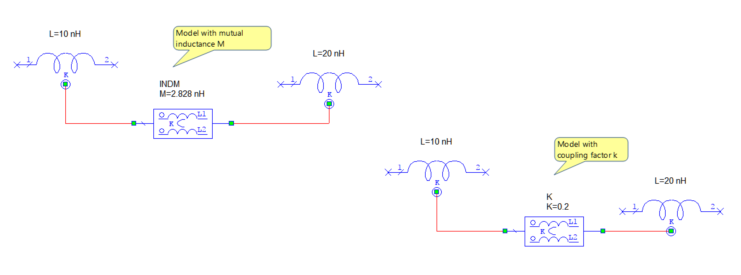
With each new tool, the user has to take care of modeling.
I have to implement this one
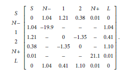
Now how can I make such coupling within range 0-1. Moreover, I am just unable to understand N- N+ non resonating nodes here in the matrix...
I don't understand this coupling matrix either. Do you know the origin of this matrix?
Well I have just sited it in a paper....
Any information regarding the concept of Non Resonating nodes?
Coupling Performing resonators 相关文章:
- problem: coupling coefficient for two hairpin resonators
- Loose Coupling for a coaxial resonator
- Methods of decreasing the coupling between two closely placed antennas
- Re: Polynomial synthesis in coupling matrix technique
- Capacitive coupling between coaxial and coplanar circular coils
- Increasing stages coupling without increasing capacitance in TRX