Twin FET DBM for simple broadband dsb transmitter.
I want to use this in my receiver http://qrp.gr/allbander/index.htm to make it a transceiver, without the need to re-set the offset at any frequency.
Can you suggest me the circuit components values and FETs to use?
How much input carrier and audio signal shall I feed to it?
Can I use a BJT instead of T1 and get the out of phase AF signals out of it's collector and emitter? Please suggest values for the resistors for that circuit.
Can I use a potentiometer instead of T2?
The understanding of how it works is good but the schematic has problems.
1. Consider what happens to the JFETs if the balance potentiometer is set to one end of it's track. Bear in mind JFETs are majority carrier devices, you bias them off to control their current.
2. The audio transformer is floating to RF. A Choke can't act as a block to RF alone, it works in the same was as a resistive divider and behaves like the 'top' high value resistor but still needs a 'bottom' resistor to be able to reduce the voltage. You should at least add two capacitors, one from each end of the transformer secondary to ground.
In principle, any circuit that has two signal paths and a combiner, and the signals are inverted will cancel them out and unbalancing them with modulation signal will result in DSB. I still wonder why you want DSB though, as a method of transmission it has no real advantage over AM and it takes up twice the bandwidth of SSB.
Brian.
DSB is needed because it is somewhere between AM and SSB. It is worse than SSB but better than AM. You could TX and heard by SSB operated HAMs and your TX amps do not need to operate at all time.
How about this one?
I am trying to eliminate the transformers, so I have used a simple bjt phase inverter. Then I get the output using another potentiometer that feeds CD to the drains and the C-R filters out the audio from the output. There are also protection resistors in the sources now (they could be placed in the drains instead).
Does it seem ok?
It wouldn't work like that. You need the magnetic cancellation in the output inductor to eliminate the common signal (the carrier) so I would leave that part like the original circuit and wind it carefully so the two coils were identical. Bifilar winding should work well.
Bypass the JFET source resistors with 1nF capacitors or you will lose any amplification the give.
You also need to balance the audio levels from the phase splitter which might be tricky, you might need additional potentiometers in one or both audio paths.
It starts to get complicated. Have you considered a polyphase network? Not much more complicated and it produces USB or LSB directly instead of DSB.
Brian.
Indeed it starts to get complicated.
The polyphase network http://www.qsl.net/va3iul/Homebrew_R...ator_G3PLX.gif will require 4x the LO frequency so that 4 phases could be achieved and that is a problem to this simple circuit.
However, look at this one http://4.bp.blogspot.com/-gUk-QDpXG7...implessbtx.jpg it seems quite small, although my problem is that I need a broadband modulator because it will be directly driven by a broadband oscillator (1-30MHz).
I am not sure how such a circuit can perform in that sense.
Perhaps this will help:
http://lea.hamradio.si/~s53mv/zifssb/block.html
It has a good explanation of the good and bad points of different SSB TX/RX methods. The designs shown are for UHF and microwave transceivers but the principles and modulator stages are the same.
Generating quadrature oscillator signals is actually quite easy. If the frequency is fixed it can be done with a single RC or LC combination because the values are constant. For a VFO driven one, it can easily be done using a pair of logic flip-flops, it does need 4 times the TX/RX frequency to clock them but it works from almost DC to quite high frequencies. The fact that it produces a logic level output doesn't cause any problem because all the I and Q signals do is open and close analog switches anyway.
Brian.
This circuit is not a real modulator, it's just a mixer.
That circuit adds RF and AF signals then mixes them by nonlinear transfer characteristic of the FET like (a+b)^2=A^2+2*a*b+b^2
So in that way, it obtains 2*a*b that returns into multiplying and extracting of two cos signals.
Try this BJT DSB modulator which provides better than 50dB rejection of the carrier.

This is similar to the FET one. I wonder if this can have similar performance up to 30MHz?
How easy would be to make it broadband 1-30MHz? A broadband output transformer would suffice?
Why you don't consider SA612 like solution ? It's a DSB-SC Modulator and it will work 1-30MHz range..
Oh I did. It would be easy and without any transformers.
I would like to investigate how can this be done in discrete components, in the easiest way.
Just to mention, I recently learn that the 612 has only a 30-35db of carrier suppression whereas a mc1596 is better. The TL442 (sn76514) requires even less components and it is similar to the mc1496.
I will use such a chip but I would like to see what can be done discrete and how easy.
If I were you since you intend to realize a discrete modulator, I try to build-up MC1596's internal circuit with discrete components.
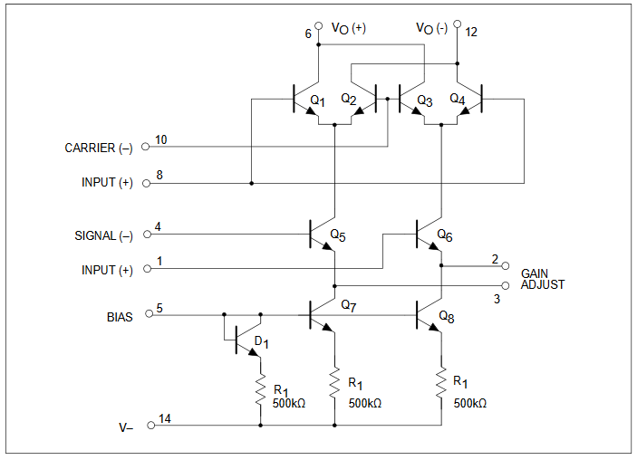
I wonder why such a complex circuit must be used.
See this example http://homepage.eircom.net/~ei9gq/exciter.html
It is a single balanced mixer and the carrier is suppressed at the output. He uses the 43 material for the core. I have to test this to see how broadband it may be.
I am thinking to try this one, but before I do so, I am trying to find out if I could somehow remove the transformer.
The first use of the transformer is to feed the diodes with out of phase RF signal. I could do this with an RF phase splitter BJT, like the one at the post of VFONE above in this thread.
However I cannot thing of a way to feed audio without a transformer. Is there any?