MIcrostrip Line with COMSOL
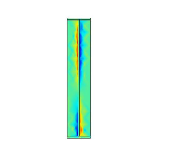
I am simply simulating a quasi-TEM mode of a microstrip line in COMSOL. I got the results as expected, but there is one problem that when I change the length of microstrip, the transmission peak frequency shifts. Can anyone comment on this.
Parameters of line:-
Substrate thickness = 0.9 mm
Substrate relative epsilon = 9.9
Width of metal strip = 0.87
Length of dielectric and ground plate = 60mm (arbitrarly choosen)
Width of dielectric and ground plate= 8 mm (arbitrarly choosen)
I am exciting with the default lumped port of COMSOL at the starting of the transmission line.
Why you're surprised ? If the Characteristic Impedance of a Transmission Line is not exactly System's Characteristic Impedance, Input Impedance will draw a small circle around Smith Charts center and will show lower impedance and higher impedance at every Lambda/4.
So, should I choose it's length Lambda/4? What about width(not thickness) of dielectric or ground plate? In literature the length and width should be infinite. But for simulations, these have to be finite.
There is no "correct" length. A frequency dependency is what a transmission line is expected to show. Plot your S11 results in Smith chart and you will see the input impedance curve circle around the line impedance value.
Substrate and ground of 4 * line width should be fine, fields that are further away should not have much impact.
In any case, for such "I modelled something and get unexpected results" questions it is useful to show screenshots of model and/or results.
You talk about unrelated different things.Your phenomena can be illustrated as ;
So, when Input Impedance is decided once, the length can be found OR length is given, Input Impedance can be found.
The images that I have attached shows the simulation of microstrip line with physical length 75mm. So as I interpret the S11 parameter plot, can I say that frequencies with lowest S11 value will propagate with minimum reflection. Why are there so many dips? In my simulation the frequency values seems to depend on the physical length of microstrip. Is there a formula from where relating frequency and physical length?


Regarding the ripple, looks at the posts above and do some reading on this topic. In #5 Bigboss provided the equation relating input impedance, line impedance and load impedance with electrical length (= length measured in wavelength). That is where frequency comes into your results and creates ripple. The same concept is explained in more detail in my old application note on EM simulation of lines, see attachment.
It is obvious that your line impedance is not well matched to the source/load impedance. This can be a correct result from geometry, or an artefact from too coarse meshing in the solver.
Analysis of RFIC Transmission Lines.pdf
MIcrostrip Line COMSOL 相关文章:
