Gilbert Cell Bias example
So for this matter can anyone please show me how to bias the Gilbert Cell or provide an explained example circuit or anything similar? I have always had trouble with biasing transistors. What i did is biasing the upper diff amps of the gilbert cell based with the voltage divider biasing method, but i got stuck with biasing the tail transistor and I've been stuck ever since. Please, I need to make the mixer for my project but it's nowhere to be found or made, the only choice i have right now is the Gilbert Cell due to the availability of 2N2222A, resistances, capacitors, barely inductors and power. I've been stuck and hopeless for some considerable time now (more than you can imagine), I'd appreciate any time or info you can give me. (I know the theory but i'm a complete idiot when it comes to making stuff breathe)
Thank you.
Take a look at similar threads listed further down this page.
In addition, have you experimented with a differential amplifier using a long-tail pair (in simulation? Its operation is not readily obvious. It helps if you input various amplitudes at the bias terminal of the transistors.
BradtheRad thank you very much for reacting to my post, well i honestly forgot to mention that I have the same issue with a simple diff amp (with diff amp I meant a long tailed pair) which makes me completely stuck.
Here's the thing, when I rely on the voltage divider biasing method regarding the upper part of the long tailed pair, the transistors work just fine, resistance values are identified and transistors operate the way they should. But once that is done, I get stuck with adding the lower part (current mirror, resistance etc) I get stuck with binding the emitters of the upper half with the collector of the lower half(in case of using a current mirror for example), upper transistors apparently lose their biasing point...
The way i see it, unless there is another method of biasing the transistors, i won't be able maintain the bias point of the upper half, and I'm stuck with a long tailed pair with its tail missing! :(
I know I'm making a very stupid mistake somewhere, but i simply can not see it, that is why I asked for a example circuit showing how biasing resistances are calculated, what biasing method is used etc.
Regarding the other threads, I wouldn't have posted this if i didn't find the solution! Trust me, I've been around this forum for years now but I've never posted since i generally find most of the problems similar to mine solved!
Post your schematic here, let's see what you did..
BigBoss I know you'll be probably laughing your head off looking at this but hey, I tried what I could ^^'
Here's a part of what I've done:
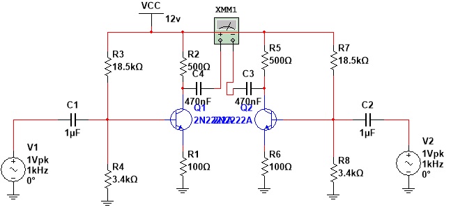
Well I made multiple grounds to show where my problem lies, the grounds below R1 and R6 are where I'm stuck.
While writing this reply, I tried to make a different bias method approach and proceeded with resistance bias and I ended up with this:
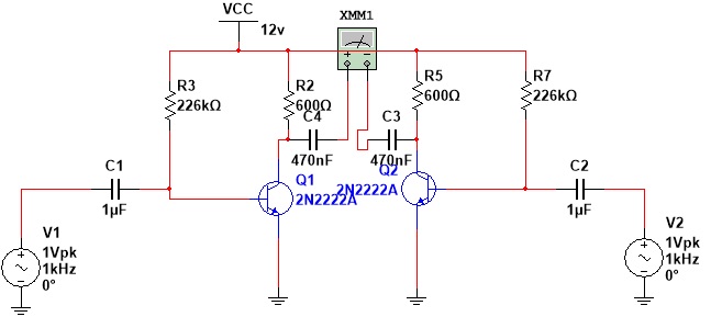
With this structure I could add a source current and it apparently works properly, the gain however is apparently very high since it works only with small signals (didn't verify or calculate anything as I just tried it before posting this reply). I tried to make a simple balanced modulator but still have the same problem, I don't know how to bias the current source as the collector is binded to the upper transistors' emitter rather than +Vcc.
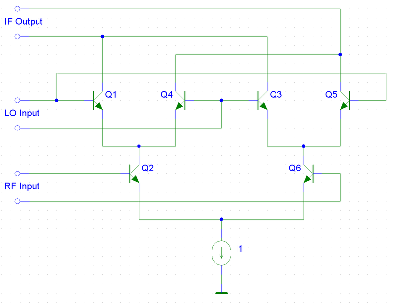
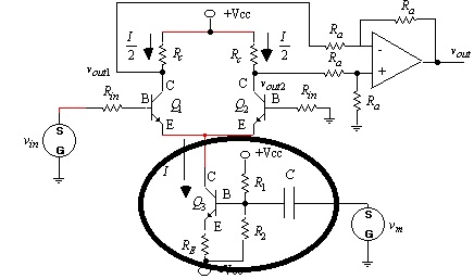
Here's an example of a simple balanced modulator I'm trying to make:
Well the lower part looks like a common collector biased apmlifier, but I have no idea how the resistances' values are calculated.. Oh and i don't intend to use the OpAmp since the best one i found here is the AD633...
Again, I'd appreciate any help you can give me!
But your circuit is not a Differential Pair.
Also, you're not driving this circuit differentially..There are serious mistakes ..
Read a bit about Differential Structures and re-spin your Gilbert Cell..
BigBoss thank you for answering so fast, please bare with me, you didn't get my point because I may have explained the matter wrongly(forgot to add the complete diff amp schematic), I've read about them even back in the day at the uni, and trust me I'll keep looking, but all I've seen until this very moment is mainly basic theory and math, all I've seen is pretty much this:
Disregard previous posts, I'll make it really simple. My question is how do you bias the transistors to make this cell work? How can I make this circuit actually work? (biasing resistances calculation etc)
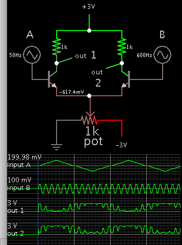
When I simulate a long-tail pair I must make many adjustments, until I observe sensible output. It is simpler to bias the tail section, by applying voltage in the negative region. This automatically makes your job easier because your inputs can be AC signals centered around 0V.
This simulation is a simple differential amplifier. Notice the outputs act similar to an op amp. The high frequency is only visible in the output when the ramp wave is near zero crossings (when it is very low amplitude). One transistor gives inverted behavior, the other transistor give non-inverted behavior. It may be necessary to adjust tail resistor and/or tail voltage if you wish to alter gain or operating range.
BradTheRad thank you so much! understood, crystal clear! Just one thing, let's say we'd like to replace the potentiometer with a transistor to control tail current like this one:
How would you bias that transistor?
The portion you have circled is a frequent method. While you're in development stage use a potentiometer to adjust bias (instead of R1 R2). Its ohm value should be high enough so it does not drown out the incoming AC signal at bottom right.
The idea is to start Q1 Q2 conducting, by pulling their emitter voltage below 0V gnd, because Q2 is biased through a resistor coming from 0V gnd. Therefore the emitter ought to be pulled down to about -0.6V.