Transmission line question and a CPW to microstripp transition question
Had a series of questions just wanted to run by, sorry if they are pretty beginner.
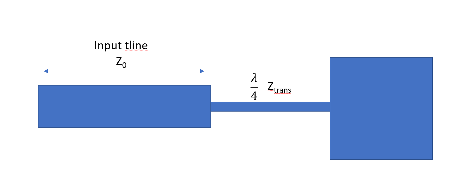
When using a quarter wave impedance match, in this case for a patch antenna, it doesn't matter how long (disregarding real loss) the input transmission line is? Will the quarter wave match perform as expected with any length?
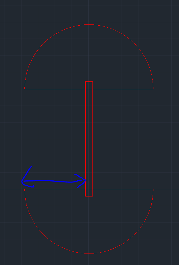
Second question, I'm trying to make some planar measurements of these patches, so I need to make a GSG probe transition to microstrip. The picture above shows my transition geometry, i use a large λ/4 radial stub to mimic a ground around my center freq. Should that λ/4 length be the wavelength of the CPW landing pad or the ustrip line?
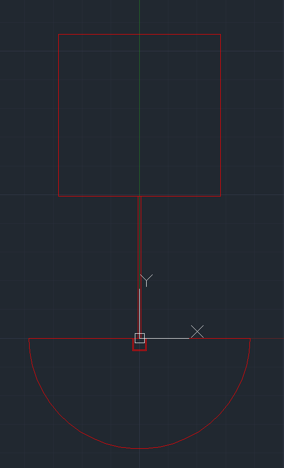
The coup de grace, the picture above shows the measurement setup i planned on to actually measure the patches. The ultimate goal to determine which patch size / feed process variation resulted in the optimum simulated results. As for calibration, I was going to start with a SOLT cal using a cal substrate. If I saw weird results using the SOLT (due to the CPW to Ustrip transitions), i was going to try a TRL cal in order to set the reference plane on the wafer and include the transition in the cal.
This leads to my last 2 questions: Do you all see any glaring holes or issues here? My eyes have been, and will be, the only ones to have functionally seen this before we spend time and money to both print and measure the antennas. So, a second option would be nice. Lastly, our VNA doesn't have the option to perform a TRL on onboard, does anyone have a handy link to the math behind TRL? You all are much more reliable than google, in these matters
Thanks in advance,
Sami
Only if patch antenna and signal source have close valued real impedances, for example 47 Ohm and 52 Ohm are pretty close in 50 Ohm system.
You may try some smith Chart tools and see what will happen. If you start far from real-valued 50 Ohm impedance (Z1=...[Ohm]) and then place 50 Ohm line of arbitrary length, then impedance will jump between initial Z1 and some other real value Z2 each 90 degrees of 50 Ohm line length.
Radial quarterwave stub length must be shorter than λ/4. Especially for thicker substrate, effective length of quarterwave stub is increased. Easiest way is to find it from simulation. For example, in my recent project λ/4 was around 4mm, and radial stub radius is 3.4mm, which is 0.6mm shorter. From what i've seen beefore usually 90 degree radial stubs are used for probes (yours is 180 degree sector). Why you are using 180 degree sector?
You may find many clues from papers on similar measurements. Usually there are two 90-degree sector radial stubs and line starting between them.
The point of the λ/4 wave match is transform the very high impedance patch to the 50Ω line. I asked the question because the equation for the λ/4 impedance matching only takes into account the input impedance, not phase.
No real reason other than, why use 2 stubs, when 1 will do. But if its a problem, i could change.
If you have 50Ω "something" on the other side, then length of 50Ω line doesn't matter as you said.
By the way, you may manufacture two prototypes, one with 50Ω line which is λ/4 longer. If there is some huge impedance mismatch, you probably will measure it, because additional λ/4 will "rotate" impedance at farthest distance.
Also I would try to keep 50Ω line length multiple of λ/2. I think this would "repeat" probe impedance to the point before quarter-wave transformer, minimizing impact of imperfections of 50Ω line.
I did not used such probes. If I would use such device I probably try to start by copying existing layouts for probe connection.