Sonnet Co-Calibrated ports
I am trying to run EM simulation on one of my IC circuits. I need to assign co-calibrated ports to the MIM capacitors so that I can later include the s-parameter files.
At one place, I have a MIM capacitor with the bottom plate connected to the ground. The top metal plate connects to two separate transmission lines. Is it possible to know how to assign co-calibrated ports and simulate in Sonnet in a such a situation?
I am confused with the co-calibrated port groups. Is it possible to know how to use the co-calibration groups and whether I need to connect to the sonnet box or assign it as floating ports?
Thanks a lot!
Hello,
can you describe in more detail what you want to do?
If you have free access to the sides, then I recommend to use box wall ports (= ground reference from the box side wall) instead of CoCal ports (= ground reference from the top or bottom of the analysis box).
I recommend to use box wall ports in this case. There is no need to use CoCal ports.
For on-chip analysis, I would use CoCal ports only where box wall ports can not be used. The CoCal ports will need to get global ground from the top/bottom of the analysis box, which is far away for typical RFIC models because of the thick Si substrate. That feed structure through the thick substrate might create parasitic coupling.
I will try to explain. Co-Cal ports can be understood if we look at autogrounded ports first. Autogrounded ports are calibrated one after another, independently. Each autogrounded port will create a via to the bottom of the box, and then do de-embedding on that feed structure, so that the effect of the feed structure (including the ground via) via is calculated and removed from the results.
Now, if you have two autogrounded ports that are closely spaced, both create a via to ground and these feed structures can couple. If the ports are de-embedded individually, the coupling of the ground vias is not removed because the calibration standards of each individual port only contains a single vias. Now, with co-calibrated port, that concept has been extended so that multiple ports can be calibrated together. Now, the calibration standards for that CoCal port group include multiple feed structures (with multiple ground vias) and thus includes the coupling between them. By including the parasitic port coupling in the calibration standard, it is calculated and removed from the results.
Example shown here on page 46-49
http://www.muehlhaus.com/files/Sonne..._EEEfCOM10.pdf
There are limits on how the ports within the same calibration group can be located, as described in the Sonnet User's Guide. It is important to understand that only ports in the same calibration group are actually co-calibrated (=calibrated using the same set of calibration standards). For ports in different calibration groups, parasitic coupling between the ports can not be removed because different groups are calibrated independently.
Now for the global ground vs. local ground of cocal ports:
Have a look at my presentation here, page 50
http://www.muehlhaus.com/files/Sonne..._EEEfCOM10.pdf
Look at pages 51 and 52 to see the actual subsections and port ground conncetion for both cases. You will see that current to the box ground (=ground of box wall ports) can only flow if the cocal ports are also referenced to the same ground. If you are using a local ground, then you force for the current that enters the local ground to exit through the attached ports (sum of all currents on local ground plane is zero).
I recommend that you have a look at the Sonnet User's Guide for floating ground reference and also contact Sonnet support to discuss a specific model.
However, in your case with the MIM, just use box wall ports.
Best regards
Volker
Hi,
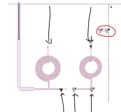
Thanks for the reply and for the presentation slides. I have attached my Sonnet circuit digram. Since the size of the circuit is too big to simulate I separated it in to several parts. The attached file is one part of the circuit.
Port 2 is the output of the circuit. Port 14H and 13H connects to a top metal of the MIM capacitor. Second metal of the MIMcap should connect to the ground.
Once the EM simulation is done, I am going to connect ports 14H and 13H together in the final Snp file and connect it to one pin of the capacitor and the other pin of the capacitor is going to connect to the ground.
Port 19M and 15I should connect to the rest of the circuit.
Port 16H is the top metal of another MIM capacitor. The second port is assigned to the second metal layer to the left. In this case it is not visible.
Is it possible to know whether my approach is correct?
Also, is it possible to know whether I need to do any modification to the Sonnet software, in-order to make use of the maximum available RAM of my computer?
Thanks a lot!
Hello again,
now I see: you want to model the layout except the MIM capacitor, and then include the MIM through the ports.
The basic approach looks correct to me:
- Port 13 and 14 should be in the same calibration group, so that the parasitic port coupling is removed.
- The ground reference is global (Sonnet box), so that current can flow from ports 13 and/or 14 to the global ground.
For the other series MIM (port 16 and ?), you can not directly group the ports because they are on different levels. I would insert a via to have both ports on the same level, so that they can be grouped.
That are my ideas regarding your model.
~~~
If this was my own model, I would probably try to include the MIM in the model, in some simplified form. First step: analyze the MIM and find some simple equivalent layout that has the same size and same capacitance. Second step: include that simplified MIM in the complete layout, instead of connecting a MIM subcircuit through ports. I do not know if my approach will show any difference in results to your approach - ideally, both will give the same results.
~~~
You have asked about using all of the available memory of your computer. Sonnet should do that automatically if your are running on a 64bit operating system.
Hi,
Thank you for the valuable information. For the second pin of my series capacitor I did not use the same group, because sonnet also gives an error. At the moment it has a different group symbol. I will try to insert a via and try to simulate.
I have another small issue. At the moment I separated my circuit in to several sections manually. Ports 15I and 19M connects to the rest of the circuit. Is it possible to know whether these ports should be aligned to a one vertical line?
Thanks a lot!
Hello again!
You get an error because ports on different layer can not be co-calibrated in the same group. If you define the ports on the same layer, you can co-calibrate them in the same group.
You mean, to co-calibrate them in the same calibration group? They are quite far away, so I do not expect much coupling. If you want to be sure, model both cases and compare if the difference is relevant for your application.
Maybe you can send me your model, so that I can have a look? My contact data is here: Contact
Best regards
Volker
Hi,
Thanks for the reply again. Regarding the previous question, I actually was referring to the dividing of the circuit for several parts. As shown in the attached file, is it ok if ports 15I and an 19M, which connects to the rest of the circuit, does not lie along the line A-B.
Thanks and Regards,
Radike
The trivial answer is: no problem, the simulation will run fine.
---------- Post added at 08:30 ---------- Previous post was at 08:20 ----------
Radike,
I have thought about your model and suggest to verify results with a second model that uses box wall ports and should be more accurate.
The short line at port 14/15 can be removed from this model and analyzed separately.
Best regards
Volker
I also see that port 19M looks really close to the Tee junction, although it is really hard to see what is going on from your picture. Could you post your sonnet file (*.son)? Then we could zoom up on it, switch layers, etc. The line between ports 14 and 15 is quite a long distance from the rest of the circuit. So, I agree with Volker, that you could you could take it out (at least for your verification test). I also agree you could use boxwall ports in most places. The only place that I am unsure of is port 16 (and it's counterpart on the other layer) because you'd have to introduce a bend by using a boxwall port on the bottom sidewall. But this bend might (?) have a very small effect.
Sonnet Calibrated ports 相关文章:
- Simulating Imported Sonnet Model Files and GDSII in Virtuoso/Custom Compiler
- Balun design gives box resonance error in Sonnet
- Simulation discrepancies between Sonnet (standalone) and Sonnet Cadence Interface
- Some problem with simulation by SONNET IE3D and HFSS
- Sonnet standard and internal co-calibrated ports giving different results
- No Sonnet Integration with Synposys Custom Compiler, Why?