2D simulation of broadside coupled stripline
时间:03-31
整理:3721RD
点击:
Hello,
i have strange results when simulating broadside coupled striplines.
It is a 2D EM simulation with Ansoft HFSS. The waveguide port considers two modes.
Impedance calculation is based on the power-current definition Zpi. Simulation freqeuncy is 20 GHz.
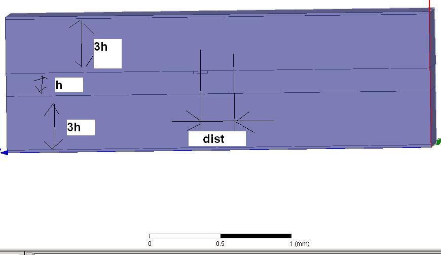
The pictures show the simulation setup, the electric field plot of mode1 (common) and mode2 (differential)
and the meaning of the variable dist.
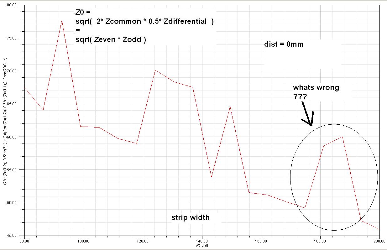
Picture 1.jpg shows the reference impedance Z0=sqrt( Zcommon*Zdifferential) for dist=0mm (strips are not shifted against each other)
and different strip widthes (same width on both strips).
The impedance calculation accuracy is 0.01 percent.
To me, it should be a smooth curve. There should be only one pair of "strip width" and "dist" to acchieve Z0=50 ohm.
Things get even more strange if I simulate for dist values greater zero.
Lets say, we have found the strip width value for dist=0mm to achieve 50ohm.
For a dist value greater 0mm, the even mode impedance should stay rather the same, whereas the odd mode value
increases (capacitance between strips decreases).
To balance this out back to 50ohm, we have to increase the strip width --> Zodd decrease, Zeven decrease --> 50ohm.
But the simulation doesnt show a clear relationship - it is confusing.
Thanks for any comment.
hfss file is attached!
i have strange results when simulating broadside coupled striplines.
It is a 2D EM simulation with Ansoft HFSS. The waveguide port considers two modes.
Impedance calculation is based on the power-current definition Zpi. Simulation freqeuncy is 20 GHz.
The pictures show the simulation setup, the electric field plot of mode1 (common) and mode2 (differential)
and the meaning of the variable dist.
Picture 1.jpg shows the reference impedance Z0=sqrt( Zcommon*Zdifferential) for dist=0mm (strips are not shifted against each other)
and different strip widthes (same width on both strips).
The impedance calculation accuracy is 0.01 percent.
To me, it should be a smooth curve. There should be only one pair of "strip width" and "dist" to acchieve Z0=50 ohm.
Things get even more strange if I simulate for dist values greater zero.
Lets say, we have found the strip width value for dist=0mm to achieve 50ohm.
For a dist value greater 0mm, the even mode impedance should stay rather the same, whereas the odd mode value
increases (capacitance between strips decreases).
To balance this out back to 50ohm, we have to increase the strip width --> Zodd decrease, Zeven decrease --> 50ohm.
But the simulation doesnt show a clear relationship - it is confusing.
Thanks for any comment.


hfss file is attached!
one last try !
broadside simulation stripline 相关文章: