How to choose the right components for the following project?
时间:03-30
整理:3721RD
点击:
Hello,
Im doing a resonant inductive coupling system as my project.
A transformer used to step down the wall outlet (230V/50Hz) to 24V @ 3A center tap, to be used as the input to a rectification circuit consisting of bridge rectifier and a filter cap.
after that, there is a crystal oscillator circuit operation at 13.56 MHz followed by class B (N-P) power amplifier to amplify the oscillator output to the transmission coil.
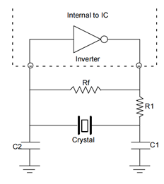
oscillator circuit diagram can be shown here
*( The output of the oscillator is not directly connected to the transistor gates, an additional operational amplifier were used to reduce the crossover distortions. A negative feedback loop is connected the output of the transistors to the inverting terminal of the op-amp, the oscillator output connected the non-inverting terminal and the output of the op-amp is connecting the transistor gates).
this is simply, how my transmission circuit would look like.
my problem is, how to get the right value of the components that operates at the specified frequency and also taking into account the voltage & current feeding the circuit, such as P and N Transistors, op-amp, and the IC Hex-inverter which completes the oscillator circuit.
also which type of transistors should be used in this project Mosfet or Bjt?
Your responds will be much appreciated..
Thank you..
Im doing a resonant inductive coupling system as my project.
A transformer used to step down the wall outlet (230V/50Hz) to 24V @ 3A center tap, to be used as the input to a rectification circuit consisting of bridge rectifier and a filter cap.
after that, there is a crystal oscillator circuit operation at 13.56 MHz followed by class B (N-P) power amplifier to amplify the oscillator output to the transmission coil.
oscillator circuit diagram can be shown here

*( The output of the oscillator is not directly connected to the transistor gates, an additional operational amplifier were used to reduce the crossover distortions. A negative feedback loop is connected the output of the transistors to the inverting terminal of the op-amp, the oscillator output connected the non-inverting terminal and the output of the op-amp is connecting the transistor gates).
this is simply, how my transmission circuit would look like.
my problem is, how to get the right value of the components that operates at the specified frequency and also taking into account the voltage & current feeding the circuit, such as P and N Transistors, op-amp, and the IC Hex-inverter which completes the oscillator circuit.
also which type of transistors should be used in this project Mosfet or Bjt?
Your responds will be much appreciated..
Thank you..
A state-of-the-art 13.56 MHz RF power stage would use class E/F respectively hard switching output stages rather than class B for effective operation.
In the said power range, fast MOSFET as used in recent MHz SMPS designs can work. Output filters are needed to "reflect" the harmonics power back to the switcher.
By the way, does your project also refer to the feasibility of RF power transmission in terms of existing EMC and safety regulations?
Thank you for your feedback..
but how will i know that my project is within the existing EMC and safety regulations?
choose components project 相关文章:
- How to choose optimal wire width of spiral coil to attain high q factor?
- how to choose optimal length and width of microstrip lines in a patch antenna array
- Question on ADS: choose view (of a component) for simulation
- how to choose "PNP-NPN" mosfet transistors?
- two components terminology from ADS to CST schemtaics question
- generate components in layout - advanced design system 2014
