What's the problem with radiation pattern (its urgent)
What radiation pattern do you expect based on the expected current distribution in the PIFA? Can you post an image of the antenna, and the pattern?
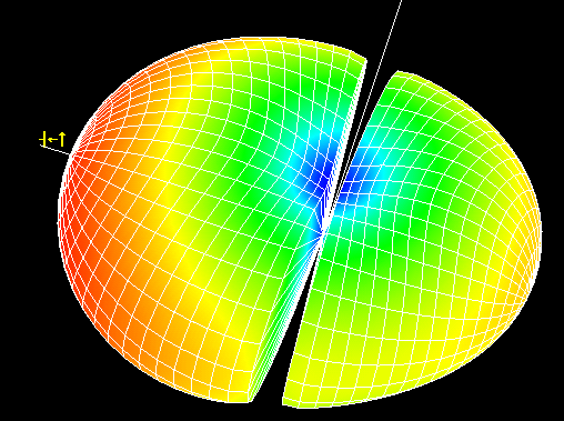
I can't see the antenne in the pattern, but I think you have a problem with the missing radiation at zero elevation (theta = 90), and your antenna is in the XY plane.
Probably you have a dielectric layer. This is standard an infinite layer (though your antenna will of course not have an infinite dielectric layer). So the "notch" in your radiation pattern is because of the infinite dielectric layer, it will not be present in the actual antenna. A wave can't propagate parallel to such a layer, therefore you don't have radiation under zero elevation.
I don't know the version of your IE3D, but newer version support finite dielectrics (I don't have a new version, so I can't simulate it for you).
Version of IE3d is 12. Does it support finite dielectrics? If yes then tell me how?
Thanks
According to Google it does (several references to this forum). A few years ago (2008) I had the opportunity to experiment with a version that enables finite dielectrics.
https://www.edaboard.com/thread76191.html shows how to do it. From what I remember the runtime increases significantly.
When you fill in the notches in the pattern, is the pattern according to your expectations? It is good to determine what to expect, as there is a trade off between accuracy and speed, and you may make an input error. From my experience, you have to be very careful when using finite groundplanes below structures that are close to that finite groundplane (as is the case with the PIFA).
Thnx...now I am not getting notches but the radiation pattern on a frequency is not gud. Its not like circle in xz and yz plane. What can be the problem?
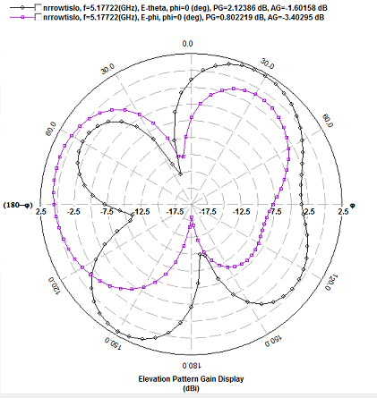
Hello Ethan, Can you post the antenna (inclusive orientation) and the elevation radiation patterns for phi=0 (XZ plane) and phi= 90 (YZ plane)?
A PIFA with ground plane in XY plane will not generate a circular shaped elevation pattern. The groundplane increases radiation in pos. Z direction and reduces radiation in neg. Z direction.
If radiation from the feed can be ignored, only the vertical part of the PIFA will generate radiation at zero elevation angle (so theta=90 degr). The pattern at zero elevation will be omnidirectional with vertical polarized field component only.
Hello Ethan, please post an image of the antenna (in such a way that I can see the orientation and the actual length or length in wave length, inclusive size of ground plane).
What is the size (adds some size values in your .png file)? It would be helpful to show a current distribution plot also, especially when it is much longer then a quarter wave (electrically).
As mentioned earlier, what do you expect?
How to do lossless simulation in IE3D? Means simulation without material losses
Hello Ethan,
You are correct, you need to go to the "basic parameters" and make the conductivity very high (for example 10..100 times the default value). For dielectric layers, set tan(delta) = zero.
This means all net power that goes into the structure (that is Pinc - Prefl) is radiated, hence directivity equals gain.
Should I increase the conductivity of dielectrics to that level?
What do you want to achieve with "increase the conductivity of dielectrics to that level", and what do you mean with "that level"?
Normally you don't specify the conductivity for a dielectric. In my posting conductivity refered to metallic layers.
If you did your simulation with finite dielectrics and finite ground plane, radiation pattern will not change significantly with changing conductivity or dielectric loss factor. Assuming that you stay within limits for real world materials.
my dielectric is infinite.......
can i get a radiation pattern without notches with infinite dielectric?
---------- Post added at 18:36 ---------- Previous post was at 17:32 ----------
Actually my institute has a old version of Ie3d which does not support finite dielectrics
Hello Ethan,
In simulation you will get the notch with infinite dielectric other then air (as shown in your second posting). This has to with wave propagation under grazing angle over dielectric material. Based on the current distribution in your antenna and some basic antenna theory (far field radiation from current segments), you can reason that your actual antenna does or does not radiate under zero elevation.
is there any mobile application for 2.23-2.27 ghz band?
Hello Ethan,
Best is to put this question in a new thread, now few reader will see it.