hexagonal lattice matlab script
Dear Jacky,
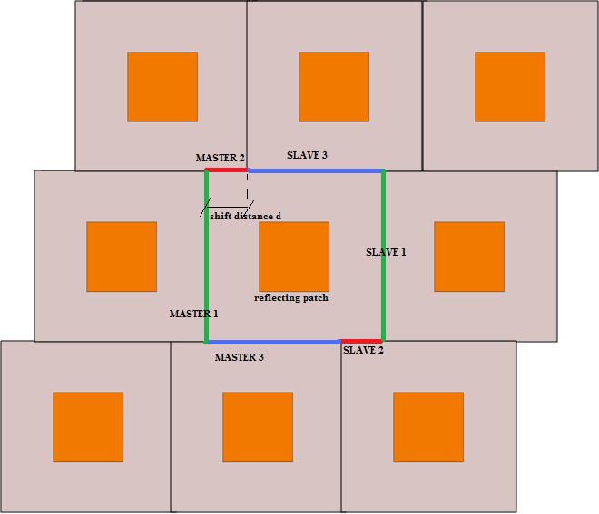
triangular lattices are useful when u have arrays with large periods (i.e.≥λ). The problem with large inter-element spacings is the formation of grating lobes which dramatically degradate the radiation behaviour of ur antenna. Introducing a skewed lattice, hence introducing a shift between adjacent rows instead of the conventional rectangular lattice, it is possible to suppress grating lobes thanks to destructive interfereces.
The first step is to evaluate the desired shift. So, first evaluate the angle at which the grating lobe is for the conventional rectangular array and then apply the desired shift to ur design.
HFSS allows the use Master/slave BC for reproducing infinite triangular lattice arrays. There are essentially 2 ways of doing it:
1) Draw a triangular unit cell (to get a 1-D skewed lattice, thus the suppression of grating lobes in a sigle plane) or an exagonal unit cell (to get a 2-D skewed lattice, thus the suppression of grating lobes in both the orthogonal planes).
2) Instead of drawing a more complicated shape for the unit cell, it is possible to use alternated master-slave BCs.Let's suppose we want to simulate a reflectarray of square patches in HFSS with a skewed lattice as shown in the picture. The configuration of Master/Slave to be used is clearly shown.

Now u can excite the structure with a plane wave for example.
In the case u wish to analyze both the orhogonal polarisations (φ=0deg and φ=90deg) as for quasi-optical amplifiers or for FSSs, there"s the need of using Floquet ports. In the attached HFSS file u will find the exact setting for Floquet ports.
Hope this helps.
Ivan
Dear Ivan:
Thank you very much for your detailed reply. After reading, I have two questions as follows:
1. I did not understand how to determine the desired shift. Could you tell which book or article describes related theory?
2. Could I exchange the position of each pair of master/slaver B.Cs? And is the cell modeling unique ?
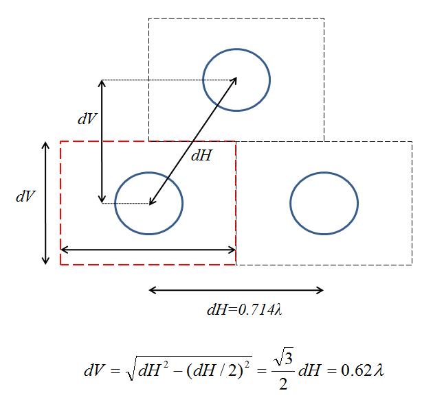
3. I want to simulate equilateral triangular periodic array. It is an example of "Theory and Analysis of Phased Array Antennas" written by Amitay,N. The array lattice is in the document. The distance between circular waveguides is 0.714lamda and the waveguide radius is 0.34lamda. How to model this infnite array in HFSS?
Thank you very much for any helps
Regards,
jacky
1) As for the calculation of the shift u can refer to these articles:
a) A High-Gain 58-GHz Box-Horn Array Antenna with Suppressed Grating Lobes, Sehm et al.;
b) Planar 64 element millimetre wave antenna, Sehm et al..
2) You can exchange M/S BCs. The important thing is that BCs are alternated.
3) Draw a rectangular unit cell in the sense u draw a rectangular sheet where u apply PEC boundary. If the diagonal distance (as I guess from the file u attached) is equal to the horizontal, that's how I would size the unit cell:

-Draw an airbox over the ground plane assign radiation to the top face;
-Draw a cylinder under the under the ground plane (your waveguide) and assign PEC to the sidewalls;
-Create an object from the upper face of the waveguide and subtract it from the ground plane the way u get the aperture;
-Place the wave port;
-Assign the Master slaves in the way you learned for triangular arrays at the airbox sidewalls;
The model should look like what follows:

And it"s done! I hope it is quite clear.
I.
Dear Ivan
I did not draw a right cell as your instructions. Because I found that dv in the picture you gave is 0.62lamda, but the waveguide radius is 0.34lamda, I can not fill the waveguide in the periodic cell. I have no idea about it. Could you help me again?
Regards.
Jacky
I need to have a look at the book u mentioned. Unfortunately I do not have it. I need to read carefully and try to understand the exact scheme. You'd better upload a pdf document of the part u are interested in. You didn't specify whether the unit cell must be square or not. Try to upload a scheme with all the distances horiz., vert. and diagonal clearly shown. I will try to draw the HFSS model. But if you tell me that the cell is square things become simpler 'cause u have the same dV and dH. Just let me know. And let me know the frequency u want to work at.
I.
Dear Ivan
I have uploaded the related documents. And I have the whole book, although it is a scanned format. If you want to read it, I can share the book with you. Thank you very much for your attention about my questions.
Regards,
Jacky
Hi,
I had a look at the files. As I indicated in the drawing, d=diagolal distance and b=dH must be equal with each other ( 0.714lambda) while the vertical distance is calculated to be sqrt(d^2-(b/2)^2)=0.62lambda. Maybe, when they refer to 'a' they say the radius but they mean the diameter of the waveguide (0.34lambda) otherwise the hole is larger than the vertical size of the unit cell. Try choosing 'a' as the diameter, not the radius.
Otherwise u can try to choose the radius of the circuilar waveguide by a few simple consideration. Once u fix the unit cell, try to evaluate the radius of the waveg. the way the only TE11 mode is excited in the range of interest. To aim at this u should use equations of circular waveguides. It's easy, u can develop a short program in matlab to calculate cutoff frequencies of TE11 and first higher mode.
I.
Dear Ivan:
First, the radius is really 0.34lamda, because I see this example in other IEEE document. Actually, It is also hexagonal array, so could I make a hexagonal periodic cell?
Regards,
Jacky
Dear Jacky, the riadius is too large. So the things are two: the given dimensions b & d are wrong or the radius is wrong. Using an exagonal cell is the same thing, the problem comes out again, as u can see I prepared an example with the given dimensions operating around 20GHz and the unit cell isn't sufficiently big (or the radius isn't sufficiently small). So I don't know, that is what I see. That is what I can do with the provided information. If I were you, I would try either to reduce the radius or to make the distance larger.
I.
Dear Ivan:
Thank you very much for giving me a lot of useful information. And I made a HFSS project to model this infnite array. But the simulation result is not well agreement with the example in the book. The author used a modal expansion to deal with the infinite array. The main difference between my simulation and the example's result is that the position of bilnd spot is not coincide. Also, the lagrest S11 does not reach 1. I have no idea about the problem. Could you check my project? Thanks again!
Jacky
In this case u have no need to use Floquet Ports. I put radiation instead of it. Being the cell completely symmetric I put only one mode at the port. Did you check no higher modes are excited at ur operating frequency but only TE11? The waveguide radius is 34cm!
Moreover, try to increase the number of adaptive passes and lower the convergence limit in order to improve mesh quality. This turns out to be more accurate but also more time consuming! I couldn't find the variable R_angular. Where did you use it?
Let me know.
I.
Yes, the waveguide only excite TE11 mode. Because the frequency is 299.79MHz.
And I use SR_angular (defined in project variable) in theta_scan (defined in local variable variable). And R_angular(rad)=2*pi*0.714*sin(60)*sin(theta_scan), the condition represents an E-plane scan.
Jacky
can you please share the book.
Actually my problem is simulating an array of end fire element like vivaldi in triangular grid fashion..can you comment on this
can anybody pl. share this book ..need urgently for analysis
hi all
could i use that technique in CST?
i means that ,could i divide the walls to be master and slave like HFSS?
Yuo can do this also in CST, yes.
hi Mr. Moshik Cohen
May i know hw u assign master slave like boundary in CST for triangular lattice? Can you send me a file for that?
Thanks
Hi,
I also work with HFSS, but some friends of my from Intel work with CST and use MS - BC. I will see if I can attach some files of them.
Cheers.
Many thanks Mr cohen if you upload any example that will help us more
regards
lattice hexagonal script 相关文章:
- Generating E8 lattice with Matlab
- Position in reciprocal lattice (for Triangular real lattice) to find photonic gapmap
- Is it possible to design a sharp 90 degree bend using triangular lattice?
- Simulation of a 2-D Hexagonal Wired Mesh Structure on HFSS 11
- How can I draw hexagonal shape in CST software?
- Hexagonal EBG structure dispersion diagram with CST
