Help with HFSS simulation setup
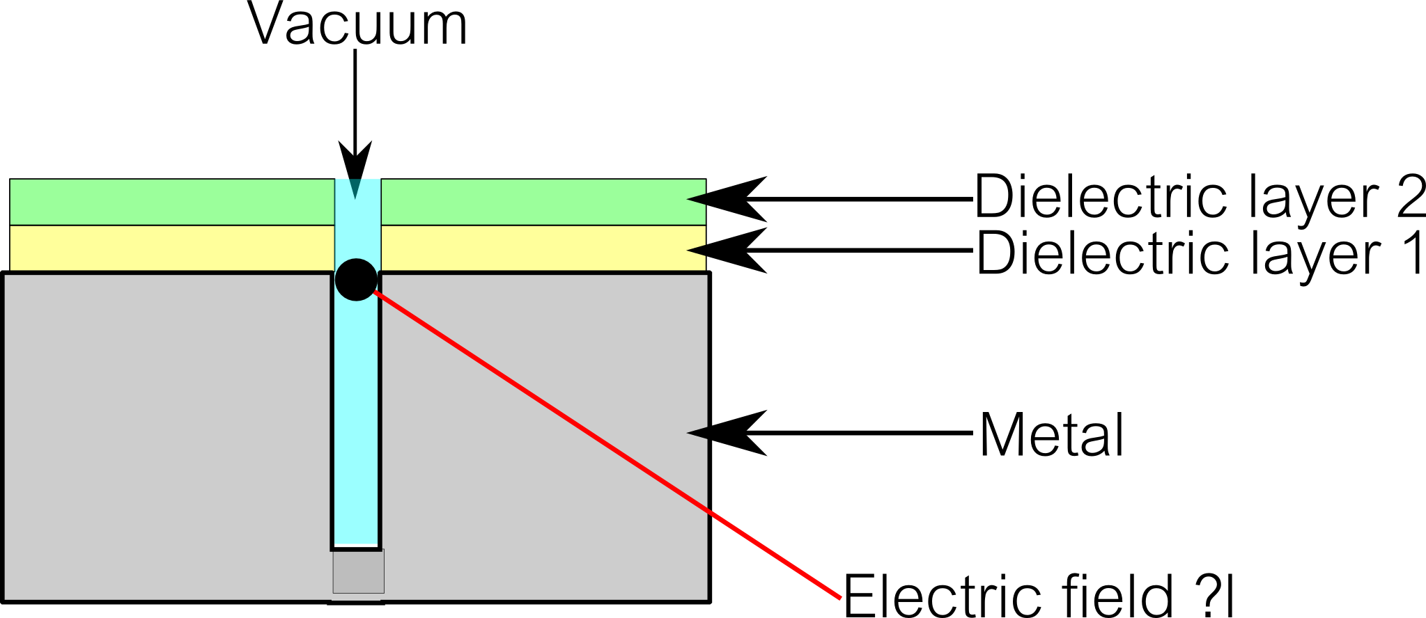
I am new to HFSS (long time user of CST) and need some help setting up a problem. I have attached a 2D figure of the simplified model of I am trying to simulate (it is a cylinder in three dimensions). This model was given to me as a .stp file and so I cannot make any changes to it. I wish to examine the fields in the region indicated in the figure. Here is what I have done so far to setup the problem,
1. Assign materials to each of the components.
2. Create a vacuum cylinder around and subtract it from the structure so the material in the hollow space is now identified as vacuum.
3. Create a PEC cylinder around the vacuum cylinder and designate as perfect E (ground).
4. Create a sheet below the metal structure and designate it as a waveguide port.
This simulation has been done previously by my collegue but I am not able to reproduce his results with the above steps. Can someone please help shed some light on what I might be doing incorrectly?
Thanks,
-P
Hi,
When you validate your model, have you got some errors ?
If not, have you put a "frequency sweep" ? perhaps you don't explore at good frequency.
Your system is a resonnant one so field could operate at particular frequencies.
Have you seen the convergence of the simulation ?
eraste,
Thanks for the response. I do not have any errors when I validate the model. The frequency I am interested in is 2MHz. I think the system is too small (compared to wavelength of 2MHz in vacuum) for it to be resonant (maybe at very high harmonics of 2MHz). The simulation runs and converges without any issues. Only the field distribution is not what was obtained by my collegue. Is my simulation approach correct or am I missing something specific to HFSS?
If it is a cylinder in 3D, the field cannot penetrate in the metallic cylinder at 2 MHz because of its dimension (cutoff frequency).
What sort of excitation do you use ? If it is a wave port, modes have to be allowed. However, i am surprised of the frequency of use.
What is the usefullness of that system ?
eraste,
The schematic is a simplified version of the problem, the full system consists of a cylinder with some hollow channels inside, but it should not matter. I use a waveport excitation and have chosen the number of modes as 1 (should the number of modes be increased?). I am suprised by the frequency too! But at present, all I am trying to do is replicate what my collegue has done previously and therefore using the exact same conditions he used. I suspect that the results would be the same for a DC (static) case (Long wavelength at 2MHz is a good approximation to DC in this setup).
Well,
When you define a waveport, in the definition windows there's a tag where you can define "number of modes".Here is a snapshot :
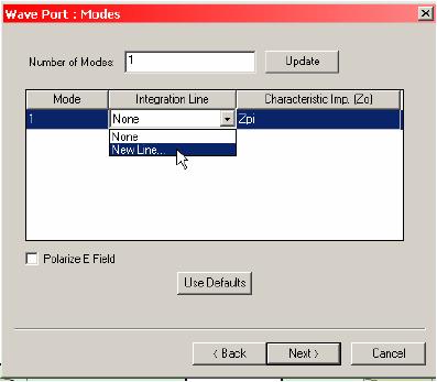
You can also increase the number of modes but if you select a single frequency of analysis, you can not see probably all the modes except if you increase the frequency or make a sweep.
Good work
eraste,
Thanks for showing me how to define an additional number of modes. I'll try this, with a frequency sweep, and let you know if I get any closer to my collegue's results.
You can also play with the converge settings for using more mesh refinement steps. Or you can increase the mesh and check if it changes the results.
Another idea is to increase the solution frequency and then using this mesh for a 2MHz simulation.
flanello,
Apologies for the delay. I'll try out your suggestions and let you know if I any of them work.