Microstrip Filters : Air ,PMC or PEC side walls?

Hi
I am a bit confused about the simulation of these microstrip structures.
Which kind of boundary condition should be used, open side walls ? PMC side walls? PEC side walls?
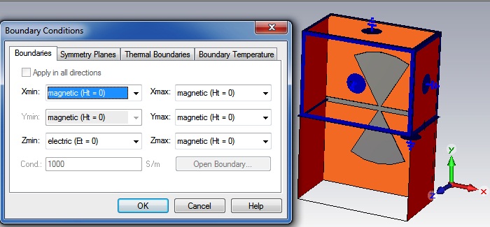
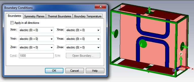
In CST Help Example files sometimes used PEC ,sometimes PMC or open ?
Which kind of boundaries i should use?
hi
u can use radiation box for it and its work as a PML and also u can chose it in new version as a PML
why radiation box ?
why not PEC or PMC ?
in CST help examples it used PMC ?
please expalin to me
do you have any hfss or CST file like this structure?
Yes. I agree in such situations, what HFSS examples show is the use of Radiation box i.e. Radiation boundary conditions. I don't know anything about CST's view on the problem.
Hi all
thank you all for your reply.
please look at this:


only radiation box is sufficient if u send your simulation i will check it
In HFSS you can use radiation box, but make sure that the distance between radiation boundary and each radiating element in your structure must be at least lambda/4.
hi amihomo
why in CST its not radiation box? can you explain please?
because CST uses the MoM method to solve the electromagnetic problem, but HFSS uses the FEM.
The former method is an integral equation method and does not need the infinity radiation boundary.
??
@ amihomo,
CST works on FDTD (Finite Difference Time Domain) and its also a differential equation approach. IE3D works on Integral equation based MoM.
Can you please explain your comment now for not using Radiation boundary condition in here.
@ Leon_80
I must say, as per the figures you uploaded with PEC and PMC boundary conditions, these are actually used to simulate the unit cell of metamaterials. I hope this is a filter that you intend to design. I can not say exactly but there is a pdf from HFSS on simulation of metamaterials where they have slightly mentioned the same structure as of yours.
as ashish said the CST base on FDTD but its not a full FDTD
i confused how amihomo tell that its working on moment
i heard that new CST versions has a mom simulator but u can't tell that its a mom tools because it base on FDTD method
The CST time domain solver is based on FIT, which is closely related to FDTD.
CST also offer other solvers (FEM, MOM etc.)
But the topic of boundary conditions is not related to the solver engine. It is related to modelling metal boundaries (PEC) for side walls or ground plane and open boundaries for free space/radiation. Magnetic walls (PMC) are nice for modelling symmetry, so that only a part of the model is meshed/simulated and the other part is included through symmetry.
I am a little perplexed by the answers here. Your choice of simulation box walls should as closely as possible mimic the actual usage. For instance, if there is a metal cover 0.1" above the filter, you had better simulated it with a PEC 0.1" above the substrate, or your analysis will erroneously show the filter response too high in frequency.
Thank you all for the answers.
But still there is no clear answer why in CST used PMc sometimes and PEC sometimes ?
