split ring resonator ports
i upload the matlab code for refractive index and permitivity and permeability extraction from the S-parameters based on smith paper for a SRR in https://www.edaboard.com/viewtopic.p...849&highlight=
i hope to investigate and run this code and tell me how you find it?
is it correct or no for all structures.
regards
Howdy...
Smith's paper (2005) is correct if you rework the maths for exp(j*w*t) so that you can use the results direclty from HFSS without the need to modify the phase of S21.
However, if you simulate his SRR-wire medium in HFSS using Floquet ports, you will get subtly different results that depend on the Floquet port - structure seperation. See my post on http://www.emtalk.com (my member name is kelvinjn in that forum)
If anyone has experienced this problem with HFSS I would be keen to discuss.
Cheers...
Hi every 1,
I'm working on a SRR structure, the same as from pendry IEEE Vol 47 No 11. As everybody above I need to retrieve the effective parameters ( eps, mu) from the scattering parameters calculated using HFSS. Using the retrieving approach as in PRB 65 195104 or equivalently PRE 71 036617, I would expect the same results as stated in PRE 68 065602,(negative Re(mu) and Im(eps ) and positive Re( eps) and Im(mu) within the resonance band) but the results are completely different. I probably don?t impose the proper conditions for the signs of Re(z) and Im(n)
The simulation is performed just for a unit cell of SRR
The excitation is done by mean of a waveport with the Efield parallel to the SRR plane and the H field parallel to the SRR axis
As boundary condition I use PEC for the surfaces normal to the electric field, while PMC for the surface normal to the H field, (as from Journal of applied physics Vol 90, N. 10), this should assure that the structure is seen as a unit cell of an extended periodic structure.
I attached the HFSS file, the matlab file and the data that come from HFSS and all the references I mentioned.
I hope to get some good hints.
salva
hi all,i see along discussion about the simulation of SRR in HFSS
here very good article from HFSS using floquet mode,really very good article
here it
regards to all
this is indeed a very helpful article of using HFSS using floquet ports
Abdoeng:
Very good tutorial on Floquet ports.
Thanks.
I get the exact results as the Smith 2005 paper.
Copie de SRR1.rar is the right file. u can use it.
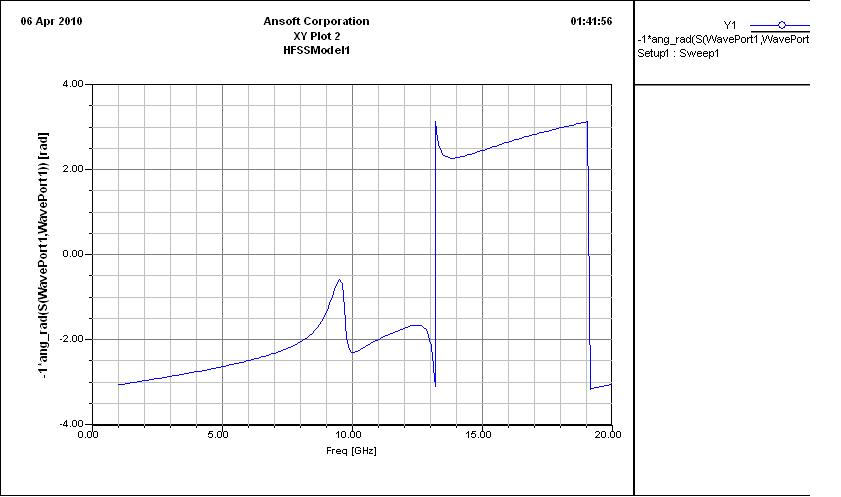
plot the S11_mag, S21_mag, -1*S11_phase(in rad), -1*S21_phase(in rad)
right click on the plotted figure, and export the plot to a text file.
use Excel to delete the first lines which are included the descriptions and deembed the phase and save the pure data file.
do not use the deembeding feature of the waveport of HFSS. do that urself in the Excel.
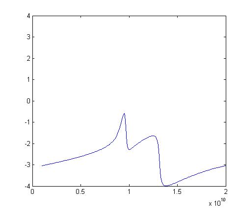
Deembeding means that where the phase has been jumped and make the figure noncontinuous, you move that part in its continuous track, for this case for the S11_phase there is a discontinuity in 13~20 GHz, edit the figure and make it continuous. hope u get that!like the image.
import them one by one in the MAtlab, and wriet:
Save S11_mag
clear
import the next
save S21_mag
and so on...
now use the attached m-file. note that d is not the thickness of the slab, it is thickness of one cell.
the HFSS file, It works:
hi, myebook
Can you talk more on deembedded process with CST MWS?
Thanks very much
Zhang
Hi,
Can you illustrate this extraction method by getting the real,imaginary parts of effective permittivity and permeability by simulating a 10 mm long of a 50Ω microstrip line on FR4-Epoxy with thickness of 1.6 mm ε relative=4.4 and loss tangent=0.022;by using HFSS and Matlab.
Take a look to my project done by HFSS,the results are not good.there's a decrease of the effective permittivity when frequency increases which is not the case,using LineCalc of Agilent ADS i noticed when frequency increase the permittivity increase also(correct)!
So what's the problem?
hi,
have got this from the smith srr+wire hfss file,
Can anybody please clarify this...
mag(S21)*(cos(-ang_deg(S21)) + cmplx(0, 1)*sin(-ang_deg(S21)))
mag(S11)*(cos(-ang_deg(S11)) + cmplx(0, 1)*sin(-ang_deg(S11)))
I have read smith paper but don't know where this equation comes from?
I will appreciate if anybody can please get back to me urgently...
I think cmplx(0,1)=j or sqrt(-1)
these expressions give S11 and S12 as complex quantities
hiii,
I am also trying to retrive parameter of ELC resonator.
But S21 is zero for this structure.
I am simulating journal of applied physics 110,014909(2011) {Ultrathin multiband gigahertz metamaterial absorber}
can anyone help me that how to retrive parameter for this structure.?
---------- Post added at 18:33 ---------- Previous post was at 18:06 ----------
If anyone simulater this srr structure or ELC resonator with master/slave boundary condition with plane wave excitation.
please upload it or reply how to use above mentioned boundary and excitation....
hello dears,
I'm a new member in this group and i'm an engineer.
I want you to help me for my problem.I work on CST SRR for metamaterials but the the result for permitivity and permeability is not true
-
-
-
can any one help me for this problem?
hey i am new to this topic. can anyone please tell me how to simulate srr? please explain how the airbox structure is made?
how to connect the ports? etc.
i want to design metamaterial base microstrip antenna pls if any tutorial send me on mail:hitesh.mathukiya@gmail.com
i don't get it yet.. is that means we didn't assign port embedding in hfss? how to do in excel?
am i wrong if i used "d" as substrate thickness, d=1.6mm?
any one have simulation in cst?!