why in my gain figure,peak is not in resonant frequency?
I have a dielectric monopole antenna in VHF band.
my gain figure is as following:
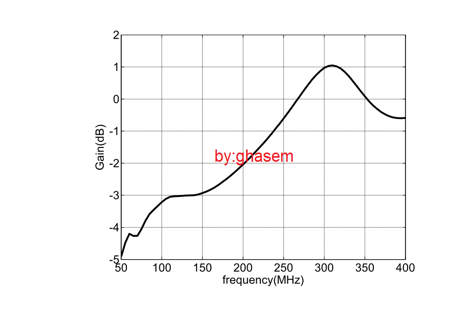
the monopole has length = 60 cm and my first resonant frequency is 115 MHz.
do I have to expect that in resonant frequency,my gain become largest?as you see in the figure,my gain at f=300MHz is maximum.
so,my design is not good?
Monopole general follow quater-wavelength rule. Can you show your current distribution at the peak frequency? Also what is your wire thickness and ground plane size?
Hello rodger.
your mean is current distribution in bottom side of the monopole in frequency domain?
my inner radius = 1.5 cm and thickness = 5 mm
ground plane is a cubic 20*20*8 cm.
Have you watched the video? It almost explains everything about monopole antenna.
Your monopole is 60cm, then the first resonant frequency is 3e8/2.4=125MHz, this is theory which is assuming the wire has no thickness.
Now your wire has a thickness of 5mm, then it will introduce extra capacitance, this is commonly known as "stretching effect" (Watch the videos in post #2). So your real resonant frequency will drop for sure, and you see that as 115MHz against 125MHz.
Now when you check the radiation pattern, its really highly depending on your ground plane, the larger of the ground plane, the closer it will match the theory. However, if you say your ground is only 20*20*8cm. Then the theory prediction is not valid, since 20cm compare with 60cm is not a ground reflector at all, it will totally change your radiation pattern. (Watch the second video in post #2), I've shown you why this is happening and how to explain it completely.
thank you very much
is there any way to download this video?
what is your offer for ground plane?
Also,I attach my monopole as following:
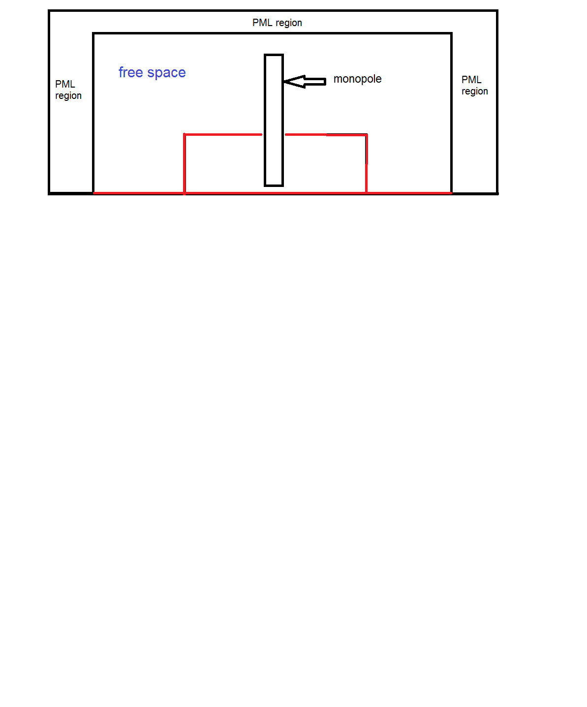
red lines are ground plane.in my design,total bottom side is ground plane (namely tangential E fields are zeros).
so I don't think that my problem to be ground plane.
It is a Youtube video, youtube allows you to download the video.
http://www.youtube.com/watch?v=Pe0LvsAWKBs
http://www.youtube.com/watch?v=e69DcWUi7N0
Looking at your structure, I am assuming all red lines are set to PEC? If this is the case, your ground plane is large enough. and the radiation patter should be toward upper direction.
Now my question is when you calculate your far-field, did you used half-space green's function? I noticed that your setup is already a half-space setup, if you use free-space green's function then your far field is going to be totally wrong. Just curious.
I can also give it a try using my own tool.
I have one question.
we know in a metal monopole antenna,maximum gain is 5.167 dB.ok?
Now,is this possible that a metal monopole antenna that sorrounded by a lossless dielectric has gain greater than 5.167 dB?
if your answer is NO,then this meant my simulation is false?
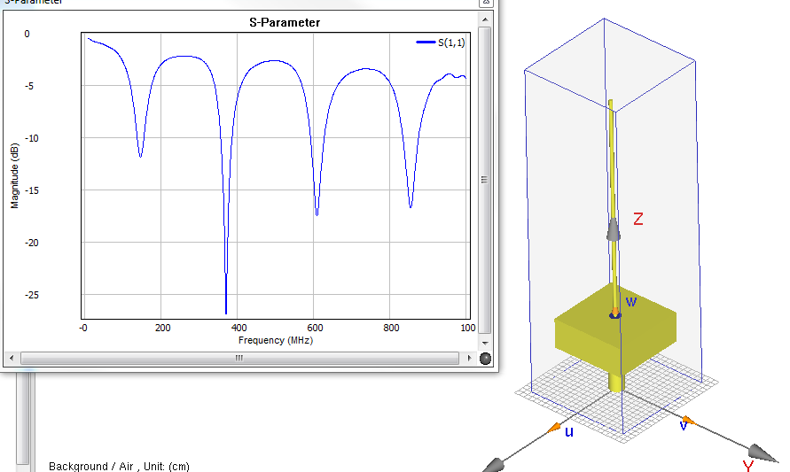

This is the S11 according to your input, 60cm wire, 20*20*8 ground box. With taflon coax feed, the quater wave length resonance freq is shifted up to nearly 146MHz, this is what I've explained in the video, its resonating together with your PEC box. However, the second resonance has much better efficient according to S11. And its radiation pattern is closer to theory. This indicates that your 2nd resonant mode is definitely working better than first mode.
thank you very much rodger.
how can I use from 2nd resonant mode?while often we use from 1st resonant mode.
also,can you give me a answer for gain value?in your simulation what is maximum gain and directivity value?
it should be less than 5.1 dB for monopole?
Well, according to what you've seen in the S11, obviously the 2nd resonant mode has better efficiency. The first resonant mode is interfered by your box structure.
The gain at 146MHz is 1.36dBi and the gain at 361MHz is 2.66dBi
can you plot a diagram for "gain versus frequency" or for "radiation efficiency versus frequency" in (30-400)MHz?
my gain figure is not same as you said.
My tool does not have that function yet.
Hi rodger.
can you look at my other question?
https://www.edaboard.com/thread292307.html
thanks