patch antenna design for 60 GHz
I am doing project on design and simulation of 2X2 micro-strip patch array antenna for 60GHz communication in HFSS.
I know how to design single patch antenna for 60GHz, but i dont know how to design 2X2 patch antenna in HFSS, if any one knows abt this plz give me an idea or if u have any example plz sent to me.
Not only 60GHZ if u any example for 2X2 patch antenna in HFSS please send to me.
Look thise :
do u have any HFSS example file for 2x2 rectangular patch array
thank
thanks for giving this examples but i need an example file for 2X2 micro strip patch antenna design fo 60 ghz in HFSS i u have any example pls send to me.......
support , you will do well.
i need an example file for 2X2 micro strip patch antenna design fo 60 ghz in HFSS i u have any example pls send to me.......
i need example for simple microstrip patch antenna for 60 GHz..can anyone send me ? thanks.
Best regards.
Hello,
For designing the patch antenna for 60 GHz, you need to consider few things e.g. feeding, thickness and bandwidth. To begin with you can design the patch for f = 60 GHz using the formula given in Balanis. You can use inset feeding, coaxial feeding or aperture couple feeding for the patch.
Once you design the patch and feeding according to the formula, you can then fine tune it in any EM solver for your specific needs. If you need a ready made solution then you can use Antenna Magus software for the designing.
Regards
Praful
@prafuledo
Any suggestion on how to design the corporate feed network for 2x2 aperture coupled antenna at 60 GHz?
@kela3kela
you have to design a simple power dividers keeping the impedance matching in mind. For example two 100ohms line joins with one 50 ohm line and the matching line should be sqrt(2)*Z0.
there are some examples given in Balanis and also in Pozar. Have a look it is quite straight forward.
The main issue with corporate feeding at 60 GHz are the losses. Try to keep it minimum.
Regards
@prafuldeo
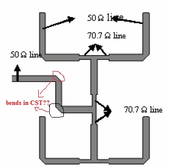
I found a feeding network for 2x2 array at 60 GHz..The image is attached below..I have few questions...

1) The feed network shown is not using 100 Ohms for matching. It only uses 50 and 70 (QWT) ohm..Is this matching correct? If so can you explain how so?
2) Could you tell me how to get those bends in CST simulator?
3) And what should be the ideal spacing between elements? Rule of thumb is Lambda/2 (which in case of 60 GHz = 5mm/2 = 2.5mm) but the paper mentions 6.5mm. Isn;t it wrong?
Awaiting replies
Regards
Dear kela3kela
To make these bends in CST, you can make a small triangle and then subtract it from the whole structure.
For spacing between elements at 60GHz, it can be more than Lambda/2 because the value of Lambda is too small at high frequencies.
Thnx fr da suggestion.
