coil around ferrite rod in Q3D
I have inserted a ferrite rod inside a copper coil (Inductor) using Q3D design, but the value of inductance is not increasing when the rod is placed inside the coil. Can any one help me out with this? Thank you very much in advance.
Did you forget to assign an μr value to the ferrite material?
Hello FvM,
Thanks for your response. Yeah the μr value is already mentioned in the properties while selecting the material. As you said assign μr value do we need to do any thing in order to assign.
Thanks in advance.
Hi Shera,
You should also add the Rod in the nets to be analyzed.
Hello Fredd,
How can we add it to nets as we cannot assign source and sink to it. Is there any way to add it to nets or how can we do that?
Thank you very much in advance.
Hi Shera,
You can assign the two ends as source and sink.
Hello Fredd,
we can do in that way for conducting materials but in this case I am using a ferrite material as core, but we cannot assign source and sink for such materials. Now how can I add it to nets? Thank you very much in advance.
Hi Shera,
May I know the resulting Inductance after adding the rod?
You can still assign a Signal net on the Rod even without the sink and source.
Hello Fredd,
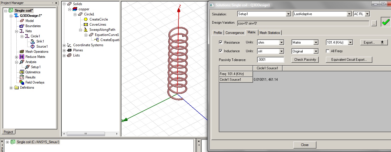
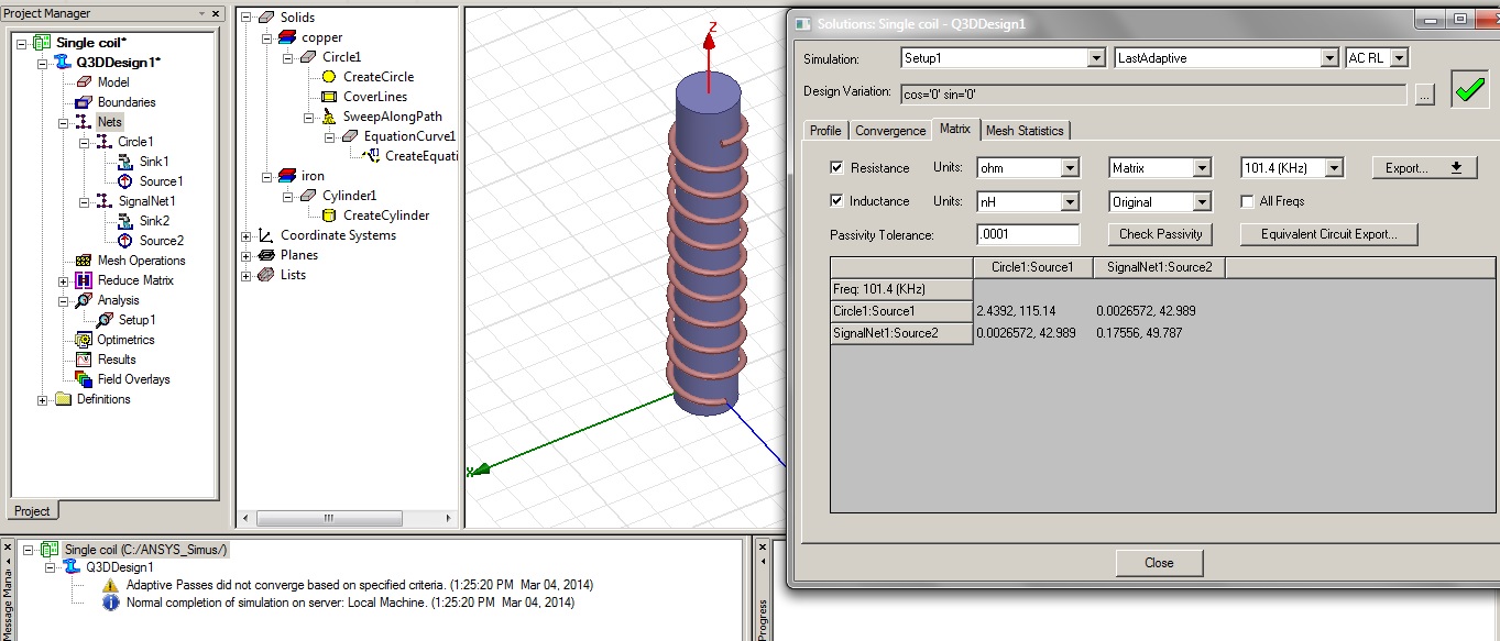
I have even tried assigning a signal net to the rod(Core) but the inductance value is not increasing it is still decreasing. When a normal coil is simulated the Resistance is 0.0001 ohm, Inductance is 463.07 nH. When a core is placed and simulated am getting a values like Resistance is 1.8423 ohm and Inductance is 175.99 nH. The result with the coil designing is shown below check it once, if there is any mistake please let me know.
This is the link for the image of the result.

The URL of the image is
http://obrazki.elektroda.pl/1318367200_1393779765.jpg
Thank you very much in advance.
Hi Shera,
May I know the mutual inductance and resistance between the coil and the rod. This could be achieved by setting the rod as Signalnet with source and sink ports.
You can assign the two ends (two faces) as source and sink. Try it first.
Thank you!
Hello Fredd,
Thank you for the help. Yes I have tried in that way also even then the inductance is not increasing. When I tried giving signal net to the rod, when there is no gap between the coil and rod am getting an error saying coil and signal are touching so I kept a gap of 0.1 mm between them. When I analysed them the results I got are shown below please have a look.
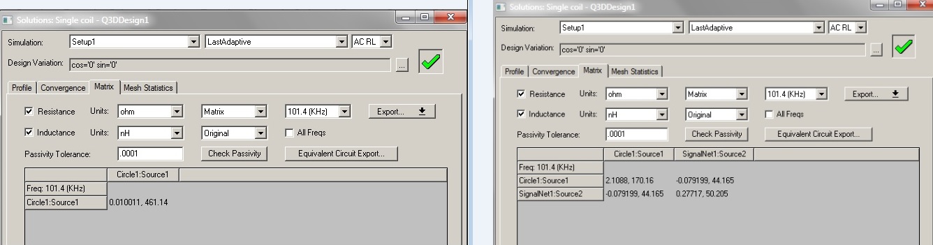
When normal coil is analyzed the result is
When a rod is placed in between with a small air gap the result is
I am using an older version of Q3d software i.e Version 12.
Thank you in advance.
Hi Shera,
There's a warning message on the second simulation. "Adaptive Passes did not converge..."
In the Setup1, you can set the AC RL max passes to 30. also set the DC RL max passes to 30. and AC CG max passes to 30.
This will ensure the convergence the simulation.
BR,
fredd
Hello Fredd,
I have tried setting the max passes to 30, I have got the following results
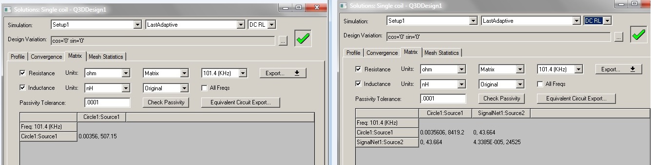
The value of inductance is same in AC RL, but it is increased in DC RL. Should we check the inductance in DC RL? If so which is the inductance value of the coil to be considered when the rod is placed. Thank you very much this was very usefull.
Hi shera,
Could you extract the S-parameters for both designs (coil, and coil+rod)? Don't include the source/sink of the rod in the 2nd design (coil+rod).
Then use Sonnet (freeware) to view the S-parameter file then extract the Inductance value.
Let' see...
How can I extract s-parameters in Q3D?
In the solutions window, click the export button and choose S-Parameters.
Hello Fredd,
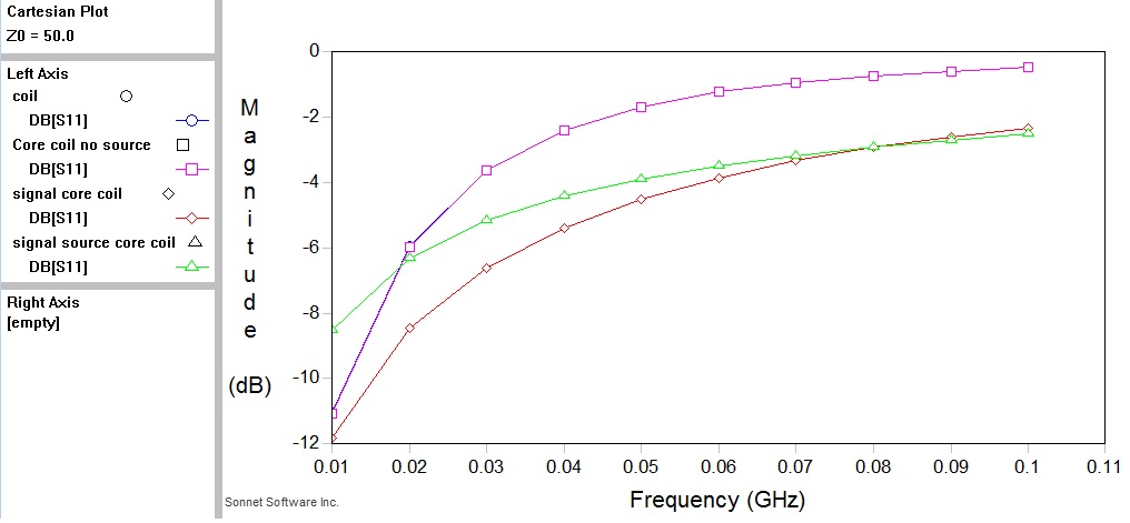
I have tried in that way and got the following graph.
I am attaching my model can you please check it once tell me what wrong I am doing...
Hi Shera,
Q3D: In the analysis setup, check the Capacitance/Conductance box. This is necessary for the s-parameter export.
Sonnet: after viewing the s-parameter file, you will see that right-axis is empty (as also indicated in the left part of the pic). Right-click on it and then add equation curve. Then select either Inductance1,2,3, and set the axis to right if you want to see both the orig plot and the new one. set the axis to left if you want to replace the current plot with the new one.
Hello Fredd,
Can you tell me how the inductance in the graph can be calculated manually with out using the parameters to get the same value.
Hi Shera,
You can see the equivalent equation body for each Inductance1,2,3.