Wrong Simulation of this cpw antenna !
i want to achieve the result of this paper i cst,bur i cant get even any result cloe to this paper,could any one help to correct my design?
please help me,that is urgent
The critical part of material selection indicates....
Often these values are not given for 1GHz , let alone 10GHz and are often too high as fiberglass content raises permittivity and loss tangent. Suppliers of Poly-amide FR4 yield better results but ε is often lower than 4.4
I suspect the material you or the author used was not same as parameters specified in article.
Dielectric Thickness must be kept small as possible and will affect impedance.
Copper thickness also has some impact.
These are some options in FR4
? Tetrafunctional Resin Tg =130°- 140°C, εr = 4.4, Tanδ= 0.024
? Multifunctional Resin Tg = 140°to 160°C, εr = 4.3, Tanδ =0.022
? High Temperature Multifunctional Resin Tg 170°- 175°C, εr = 4.1, Tanδ =0.019
? Enhanced Multifunctional Resin (Low loss) Tg 180°- 210°C, εr = 3.7, Tanδ =0.010
Keep in mind there is a tolerance on these parameters and luck is involved unless you do Monte Carlo calculations or better still put on a test coupon for controlled impedance microstrip or stripline and pay extra for controlled Z tested boards, where supplier calibrates track width for variations in εr otherwise expect 10~20% variation

Quality of coax and connector are also critical as well as torque on connect to spec.
I recommend only semi-rigid copper tubing.
thanks bro,but if i set my model according your advise then which setting(solver type ,mesh, boundary,...) must be set to achieve close result to paper?
Edaboard members who don't use CST or aren't motivated to load and simulate your design can help you much better if you show some of your results, e.g. s11/VWSR or radiation efficiency.
You didn't even tell what kind of problems you experienced.
i use cst for my project,this is my first antenna project and i dont know much about it.before i worked on wideband coupler and filter.
however i use boundary condition(open add space,lambda /4),and frequency solver domain.
one of my result is here and is not similar to the paper ,please help me to correct my fault:
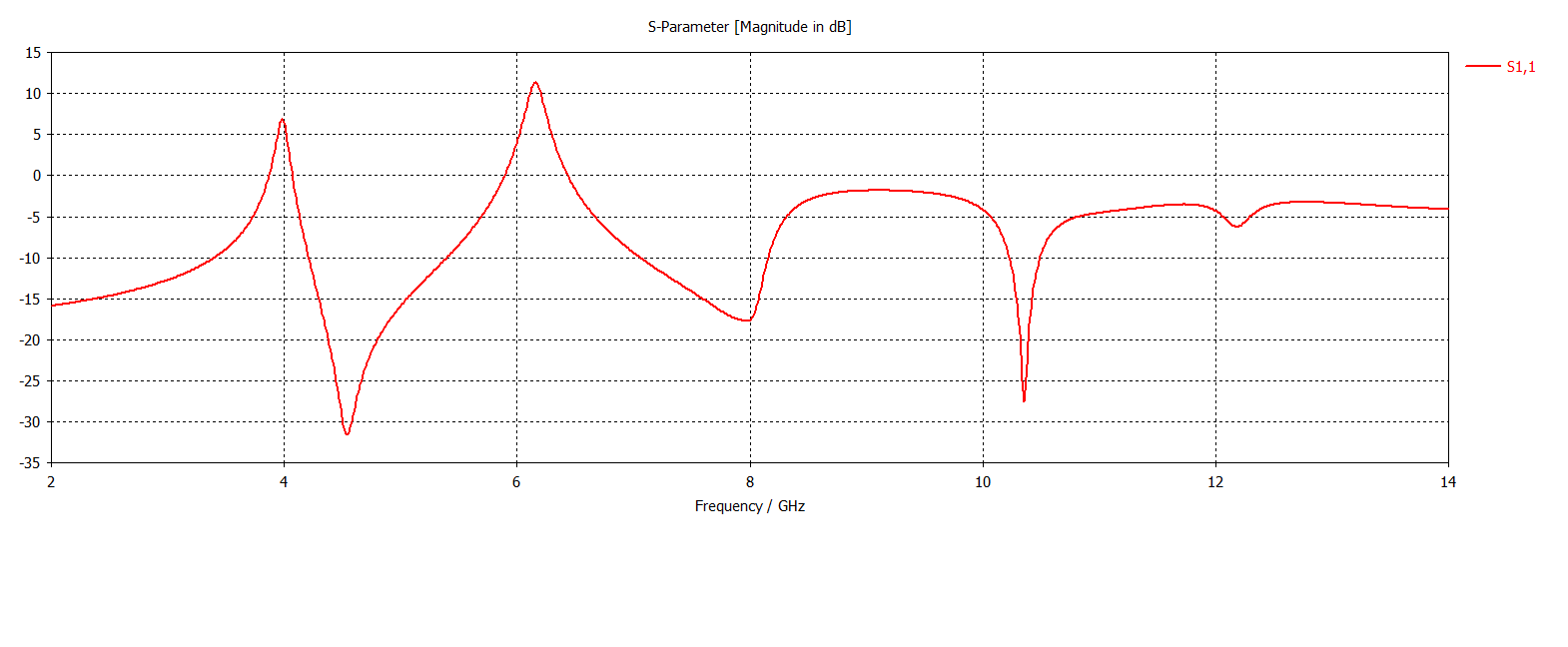
Of course, these S-parameters > 0dB are wrong.
I looked at your model and the mesh is VERY small everywhere. If you don't know how to set a good mesh for this antenna, start again with the antenna template, and use default settings.
ok,i'll do that.
but in generally could u give me a tut tu find appropriate mesh and setting solver's setting for any project?i search alot,and i just get confused!
in this new simulation i get this results,but i dont get the article results yet.
i create two vacum for gap and i used local mesh properties for that.
please check this results that .
screen shots:
hi there, finally i get this results,i read some document about MWS and this is my result,i found my mistake in mesh setting.
already i get two resonance about 3 and 6 GHz that is right but what about the third resonance?
can any one help?