Strange problem in HFSS port sizing, and result comparison to ADS and Sonnet
时间:03-30
整理:3721RD
点击:
Hi,
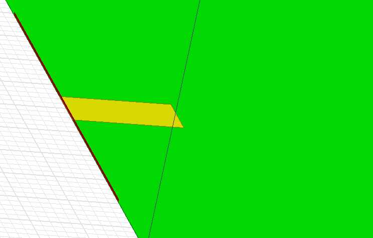
I am facing a problem with HFSS port sizing. I am simulating a simple microstrip line of width microstrip_w=50um on top of a substrate of thickness 0.3um, with perfect_E boundary assigned to the bottom face of the radiation box to act as a ground plane. The microstrip has zero thickness. the structure is shown:
I use a waveguide port with height=9*substrate_h, de-embedding, normalization impedance of 50ohm, one mode, no integration line "so Zpi used for Z0".
I am interested in the imaginary part of this line "An open microstrip is capacitive", as I will use it later to match the inductive impedance of slot antenna.
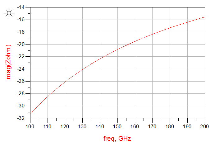
However, results change dramatically with just small change in port size. To illustrate to you more, I have made a variable port width: port_w=prefactor*microstrip_w , where prefactor changes from 8 to 16. I get near-correct results for only prefactor =13, 14, and 15 "those curves are encircled by the red circle" in the next figure:
For all those curves, convergence is reached.
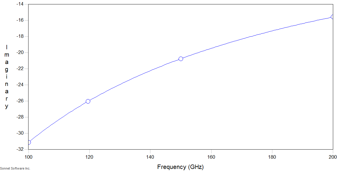
I know that those circled results are correct because I simulated the same structure using both ADS and Sonnet, and the result is nearly the same as shown below:
ADS:
Sonnet:
I even simulated "port only" with 5 modes and made sure than no higher order modes propagate.
Please tell me how to overcome this problem. The results are very sensitive to small changes in port size, "even 12.5 prefactor is very different than 12 and different than 13, and no constant trend in the resulting curves"
Why this happens and how to size the port in this case to get correct results without having to simulate using other softwares.
I need to get reliable results urgently as I will use it for a bigger problem for my degree project, and unfortunately I am running out of time
Thanks in advance
However, the result still changes with port height. Now I have port_h=prefactorh*substrate_h, where prefactorh=400 to 1000 with step 50.
So although the port now captures all the field, the results are incorrect and vary with the port height with no obvious trend:
port_h=850*substrate_h gives seemingly correct result, but I think it is an accident and nothing special with it
I am facing a problem with HFSS port sizing. I am simulating a simple microstrip line of width microstrip_w=50um on top of a substrate of thickness 0.3um, with perfect_E boundary assigned to the bottom face of the radiation box to act as a ground plane. The microstrip has zero thickness. the structure is shown:
I use a waveguide port with height=9*substrate_h, de-embedding, normalization impedance of 50ohm, one mode, no integration line "so Zpi used for Z0".
I am interested in the imaginary part of this line "An open microstrip is capacitive", as I will use it later to match the inductive impedance of slot antenna.
However, results change dramatically with just small change in port size. To illustrate to you more, I have made a variable port width: port_w=prefactor*microstrip_w , where prefactor changes from 8 to 16. I get near-correct results for only prefactor =13, 14, and 15 "those curves are encircled by the red circle" in the next figure:

For all those curves, convergence is reached.
I know that those circled results are correct because I simulated the same structure using both ADS and Sonnet, and the result is nearly the same as shown below:
ADS:
Sonnet:
I even simulated "port only" with 5 modes and made sure than no higher order modes propagate.
Please tell me how to overcome this problem. The results are very sensitive to small changes in port size, "even 12.5 prefactor is very different than 12 and different than 13, and no constant trend in the resulting curves"
Why this happens and how to size the port in this case to get correct results without having to simulate using other softwares.
I need to get reliable results urgently as I will use it for a bigger problem for my degree project, and unfortunately I am running out of time
Thanks in advance
The problem is the port size in z direction. The common rule of thumb doesn't apply here, because the ratio of line width and substrate thickness is very extreme. Imagine the electric fields around your microstrip line. The area for the wave port must capture all (or almost all) of the fields. Your port area is much too small in z direction.
Now my port is high enough in z direction to accommodate all the field "port_h=400*substrate_h", as shown:

However, the result still changes with port height. Now I have port_h=prefactorh*substrate_h, where prefactorh=400 to 1000 with step 50.
So although the port now captures all the field, the results are incorrect and vary with the port height with no obvious trend:
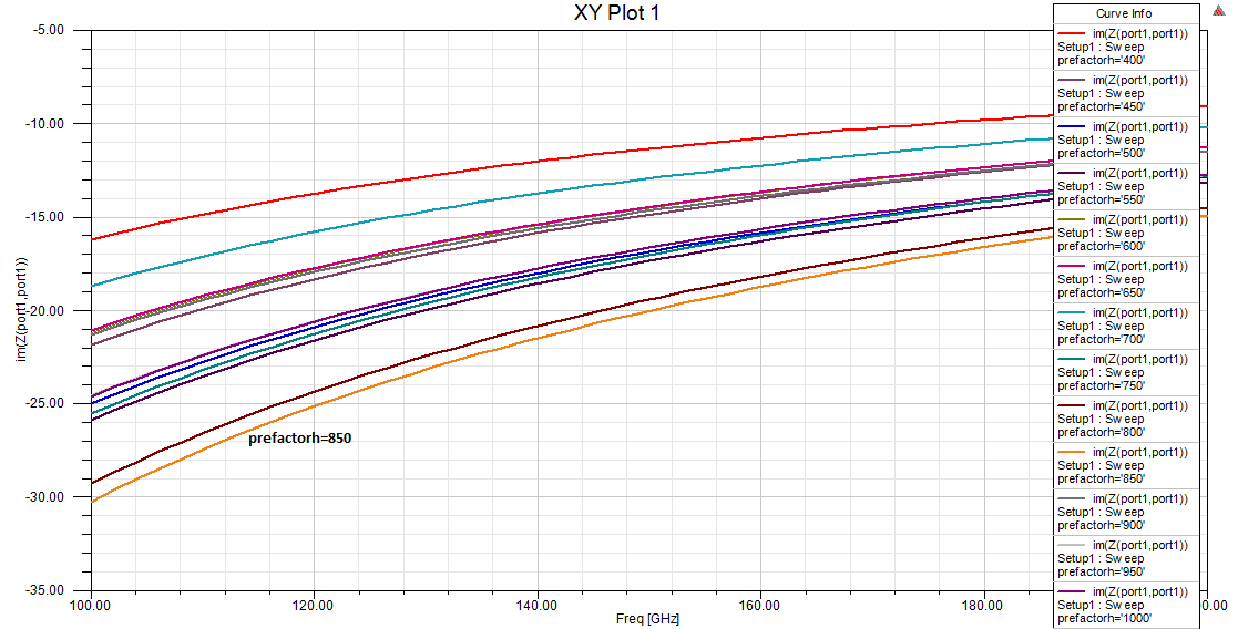
port_h=850*substrate_h gives seemingly correct result, but I think it is an accident and nothing special with it
- Exporting HFSS design model to GDSII file.
- How to check recevied power in the HFSS port?
- Importing data from HFSS and ploting in matlab
- Defining Lumped port in 3D spiral coil for different values of sweep in HFSS
- HSS Port refinement Error
- Adding/Importing PCB enclosure(step/iges file) to HFSS 3D layout