Electromagnetic Interference
I am currently working on Qi based inductive wireless charging solution for a medical device. The problem is now I am stuck with magnetic interference from the coil. When wireless charging is active, I face problem with I2C/SPI communication between my components.
I am curious about some basic physics I am not sure about
1) I know changing magnetic field can induce electric field and may disturb the electric circuits. But can a static magnetic field can also disturb the electric circuits. if yes then how ?
2) Any rule of thumb for the magnetic field strength that is probable to disturb the digital circuit in CMOS 90nm process (roughly)
Thanks
The field for charging is not static. Wireless charging reqires an AC magnetic field.
I have diffidulties to relate the question with the previous reported observation. The interfererence is unlikely occuring inside the chip. It's probably a problem of interconnects and spanned loops, induced voltage, logic thresholds.
Generally, V = dB/dt*A (induced voltage, gradient of flux variation, area)
I am using BQ51050B (Texas Instrument IC) for wireless charging and LTC2942 (Linear Technologies) for Battery State of Charge Monitoring. The u-Processor communication with LTC2942 is via I2C interface. When wireless charging is not in action, I read always correct value (say with probability of 99.9 % ) but when wireless charging is active I receive ~10% wrong values.
I decoupled the Transmitter/Receiver coil from the board so that direct AC magnetic field from the coil doesn't induce any direct disturbance but problem persists. So I guess it is a cross talk issue between BQ51050B pin (which communicates with transmitter via changing impedance) and I2C pins of LTC2942. Or may be some other issue :(
Besides all this my question was " How Static magnetic field disturbs Electric Circuits" ? It has nothing to do with the problem which includes AC magnetic field. Just wanna know how static magnetic field can disturb the electric circuits.
Thank You.
We have to look at the layout details and know the AC field parameters to understand possible intereference pathes.
Regarding static fields, they don't matter as long as they e.g. don't saturate ferromagnetic material or you have magnetical sensitive components in your design, e.g magnetoresistive or Hall-effect devices.
Radios and tv's have components shielded within steel boxes, when it is necessary to block EM between them.
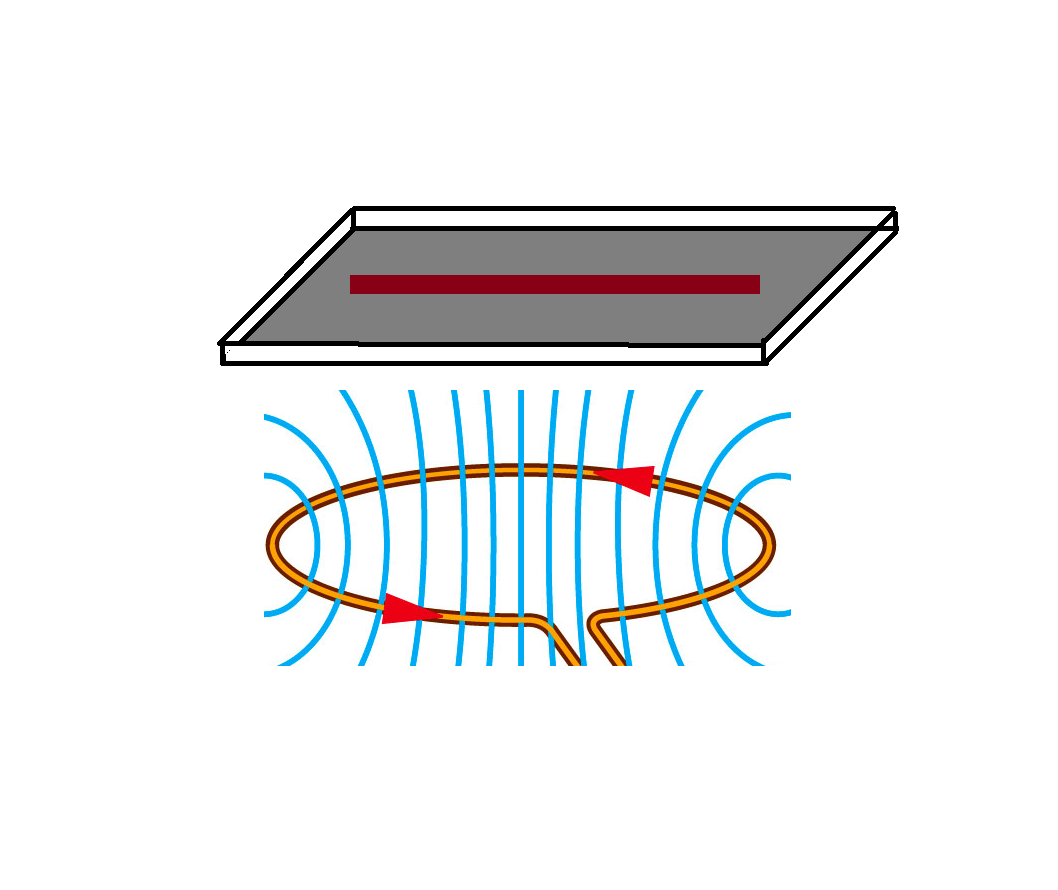
Thank you for your replies. If I place a PCB above a coil having AC magnetic field and assume that the PCB has a GND plane as a return path say complete TOP layer and a track at the bottom. Then the magnetic field produced by the coil and magnetic field produced by the PCB track (and return path of course) will be perpendicular to each other and There will be no magnetic interference. Right ?
I am taking account only the strong magnetic field at the center of the coil.
Thanks
Correct ... but do you really have (want to have) a large ground area, which possibly disturbs the AC magnetic field?
The important point is to minimize the area where your line (signal and return) collect flux from the coil below. The major magnetic field component is vertical here, so that we need to minimize the horizontal area spanned by your signal and return path. Instead of making the return path a large area, signal and return lines stacked on top of each other should also work well, if the vertical distance between the traces is much smaller than the distance to the AC coil.
Yet another option would be to twist the conductors, so that the induced field cancels. I've successfully used such field cancelling to solve on-chip coupling issues.
I would try good ferrite beads around conductor pairs to improve balance and raise CM impedance so that a small cap can shunt magnetic fields. at 1MHz.
Can you capture the noise on the signal and confirm it is what you think it is.? It should be around 15 dB S/N at those error rates. You may NEED to create an error detect signal to trigger the DSO.
Then next thing I do is try to make the error rate worse by electromagnetic coupling my finger to various sensitive cables or tracks and then shunting another finger to ground to reduce the coupling.. Then you can easily identify like paths and sensitive paths. Another method is a small closed loop wire to probe tip/ring for near field sniffing of EM fields to a DSO.
Electromagnetic Interference 相关文章:
- FREE electromagnetic simulators, rather than commercial ones
- Re: FREE electromagnetic simulators, rather than commercial ones
- electromagnetic emission from local and global grid
- Need references about numerical electromagnetic !
- Electromagnetic Field Vs Waves
- rogowski coil ..magnetic or electromagnetic