several question for transformer simulation in momentum
first way:
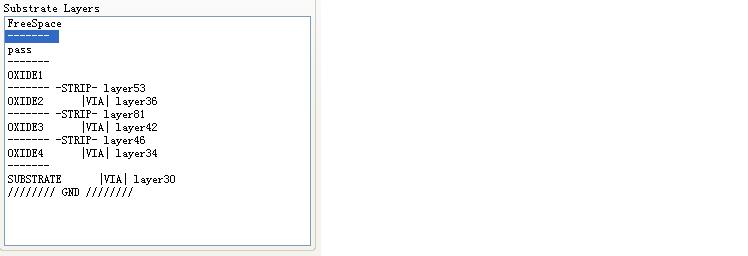
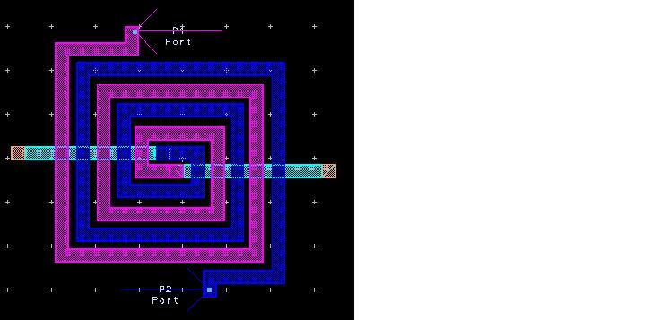
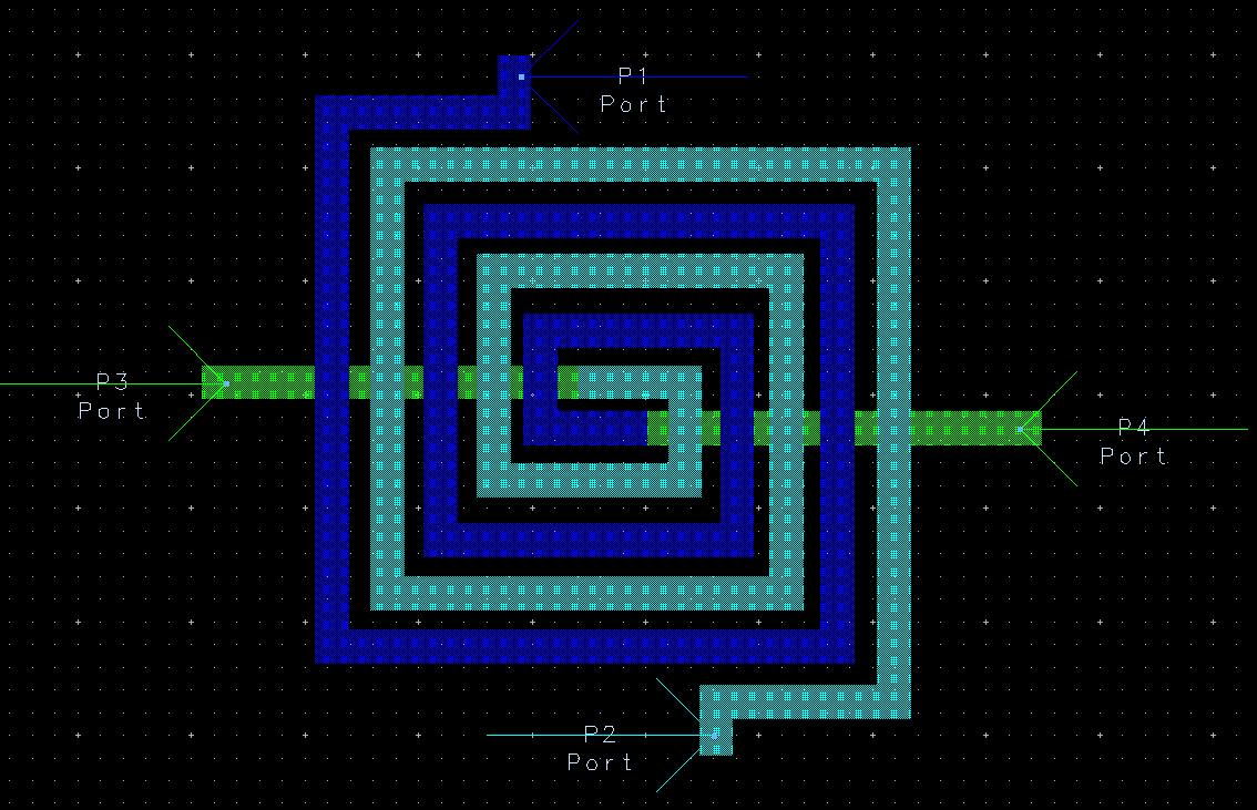
transformer in momentum
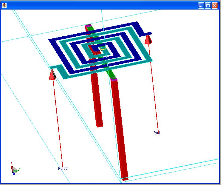
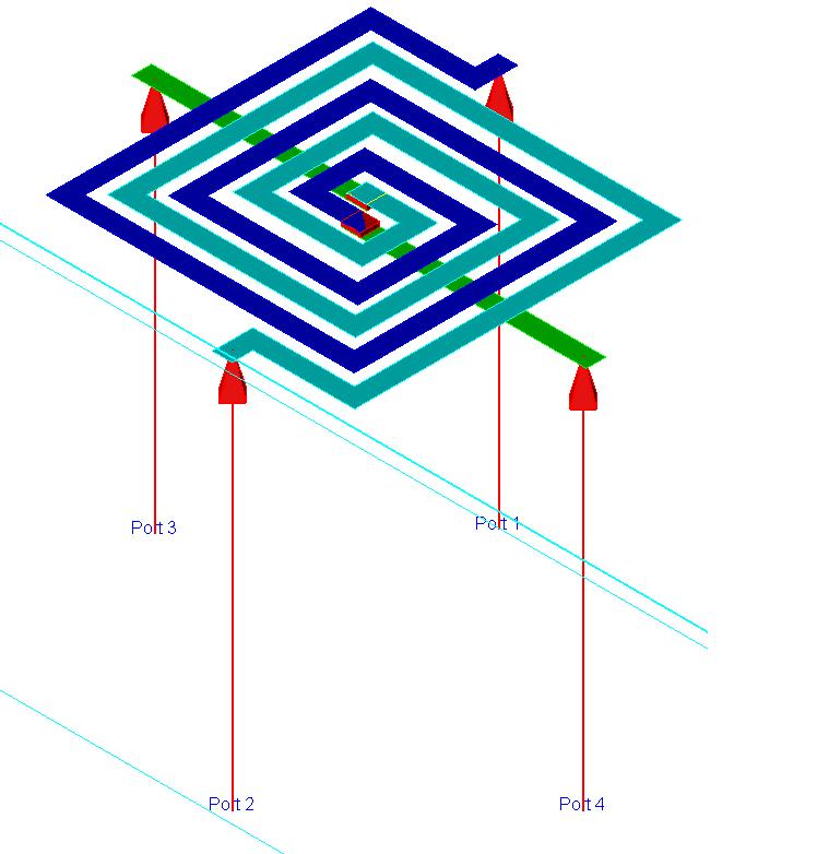
3d view
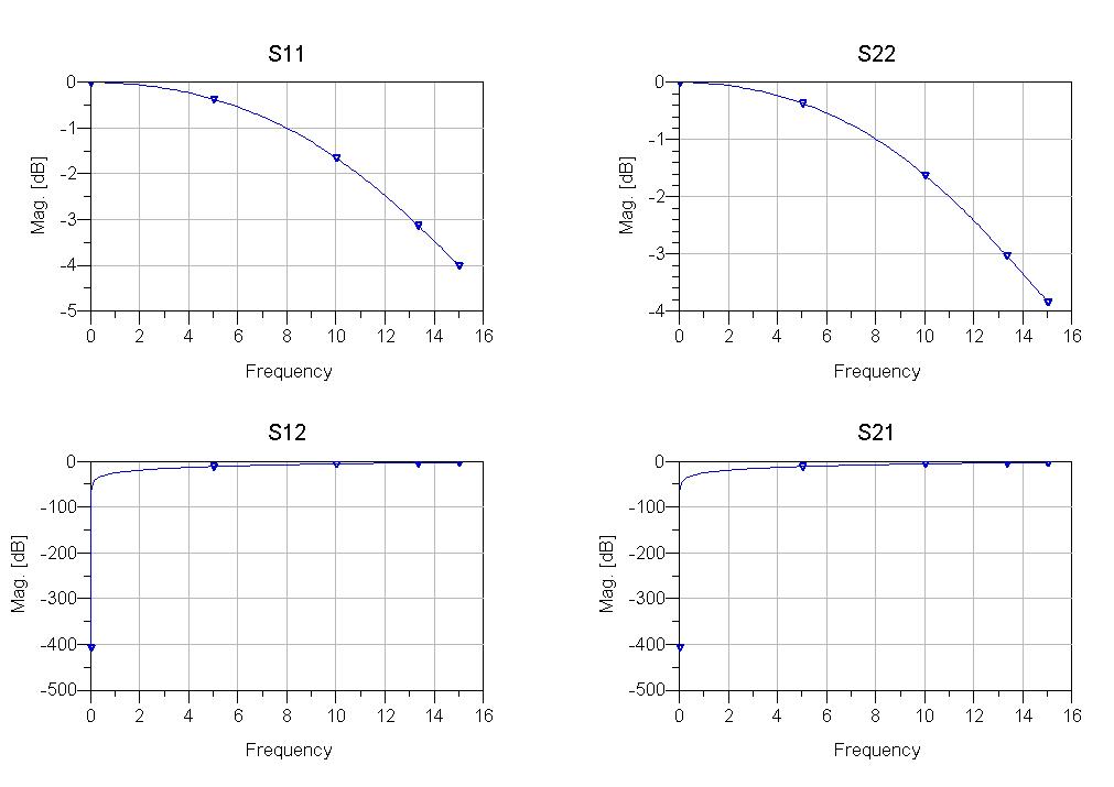
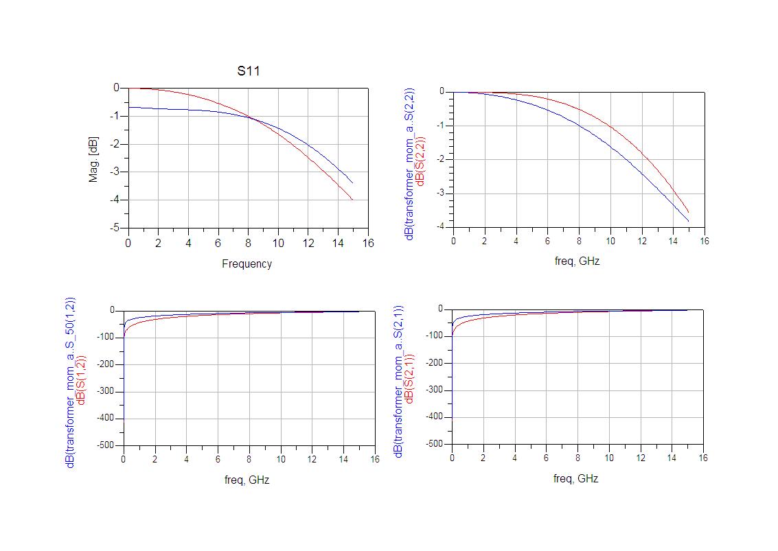
simulation results
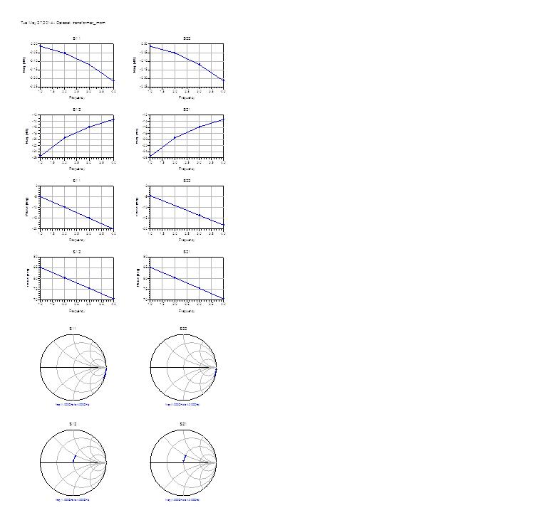
can you tell me all these setting right or not? Is this result right or not?
the second way:
transformer_2 in momentum
3D view_2
I should select the first way or the second way to simulate the transformer in momentum?
If you use through-sillicon vias, first is ok. But if you'll use your transformer as 4-port device, second setup would be more correct.
thanks!
if iI create a 4-port item with the simulation result in the second way and connect two port to ground like the first way, do you think I will get the the simulation result in the first way?
If you include the vias in the EM model, your results will include the electrical effect of the vias (self inductance of each via, mutual inductance between the vias).
If you create the short from the 4-port data, the connection is ideal and the physical via effects are not included.
From the Data Items library,I selected a data block with the same number of ports(5 ports and a ref port) as my inductor. Is the ref port the port 6 of my transformer in momentum?
maybe, I should select S6P and not S5P!
I tried in these two way:
the first way:

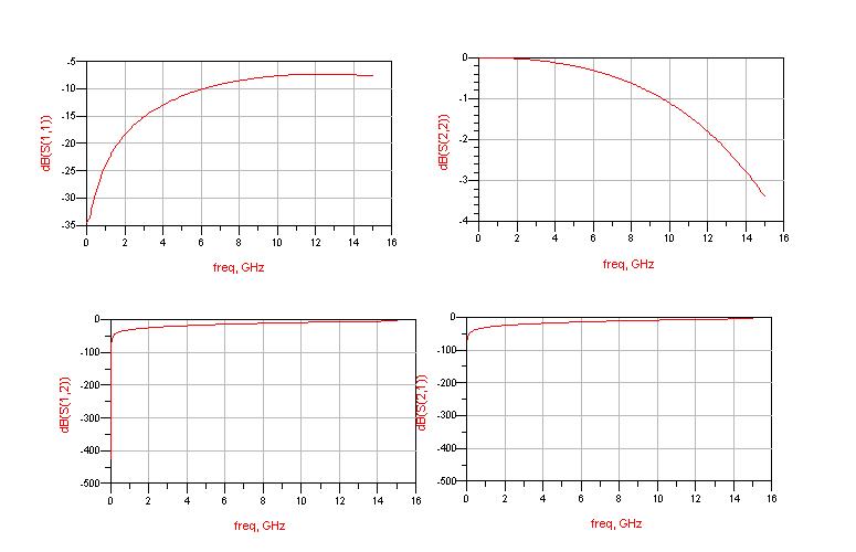
the result:
the second way:

the result:
the S11 in the first way is not equal to the S11 in the second way.
why?
I have attached the momentum project here, including the GDSfile, streammap file and the substrate file.
Help me!
If you place 5 ports in layout, you should take a 5-port item, 6 ports -> 6-port item. The additional ref-port of the item is the definition of your ground. You should connect your system ground for example there. It's not a port you set in your layout.
I tried in these two way:
the first way:
the result:
the second way:
the result:
the S11 in the first way is not equal to the S11 in the second way.
why?
I have attached the momentum project here, including the GDSfile, streammap file and the substrate file.
Help me!
You are comparing apples and oranges.
In the first model, the second pin of your transformer input coil is shorted to ground (by the via that you have drawn).
In the second model, the second pin of your transformer input is connected to a port (50 Ohm), and not connected to ground. If you want to compare both models, in the schematic you need to connect the second pin of your transformer input to ground. Only then, both models are approximately the same.
I didn't connect the second pin ground, I connected the third and the fourth pin ground.
S12 ,S21 and S22 are all the same, why S11 not?
It is wrong obviously! S22 is decreasing, but S11 is increasing. I don't know why.
Take your second model, it has 4 ports as I can see. Use in a schematic a 4-port item. Connect the Ref pin to GND-symbol. Forget about the first model as long as you don't want to use any through silicon vias, as I mentioned! From your layout, P1 and P4 are first winding, P2 and P3 are second winding. Connect for example in your schematic to P1 and P4 a port and at P2 and P3 a second port, run a simulation and calculate from the s-parameters z or y parameters (there are functions in ADS to do). From these values you can calculate the primary and secondary inductance, mutual inductance and so on because to understand your transformer, s-parameters are not very useful, I think.
to volker@muehlhaus "You are comparing apples and oranges."
you are right. I set the port impedance of port 3 and 4 to 0.001, S11 decreased too.
but both models are not the same.
to :johnjoe
I still think this defference is too big!
Why?
Which difference? Between both setups? Sure there is a big difference, these are totally different circuits.
Why not connect these ports to ground (schematic symbol GND)?
As I wrote above: one of your models has an ideal ground path, the other has a physical via.
To understand your simulation results, start simple: check the input impedance into the primary coil. Extract the real part of the input impedance => resistance. Extract the imaginary part of the input impedance => calculate inductance of the primary coil. Then, move on to the other coil. Then, calculate the coupling factor k. Check if your results make sense. If they don't make sense, check your circuit simulation and port definition ("where does the current flow?").
for"these are totally different circuits."
one of my models has an ideal ground path, the other has a port with a 0.001ohm port resistance (Port resistance cann't set to zero in momentum. I cann't get a four ports item, if I just connect them to ground in momentum). I don't think they are totally different circuits. I just donn't know why the simulation result are totally different.
[QUOTE=volker@muehlhaus;1354314]Why not connect these ports to ground (schematic symbol GND)?
Port resistance cann't be set to zero in momentum.
My purpose:
draw the layout of a transformer in cadence => export the gds file => import the gds file in ads momentum => simulate the transformer in momentum => get the S parameters => built a S4P data item => simulate the data item to get the same S parameters => extract the equivalent circuit model parameter of the transformer based on these S parameters => simulate a transformer based circuit in cadence with the equivalent circui model.
I need a four port transformer, so I can not just connect two port to ground when I simulated the transformer in momentum.
Port resistance cann't be set to zero in momentum.