Extracting broad band RLC model from S-parameters for a DGS band-stop filter.
时间:03-30
整理:3721RD
点击:
Hi,
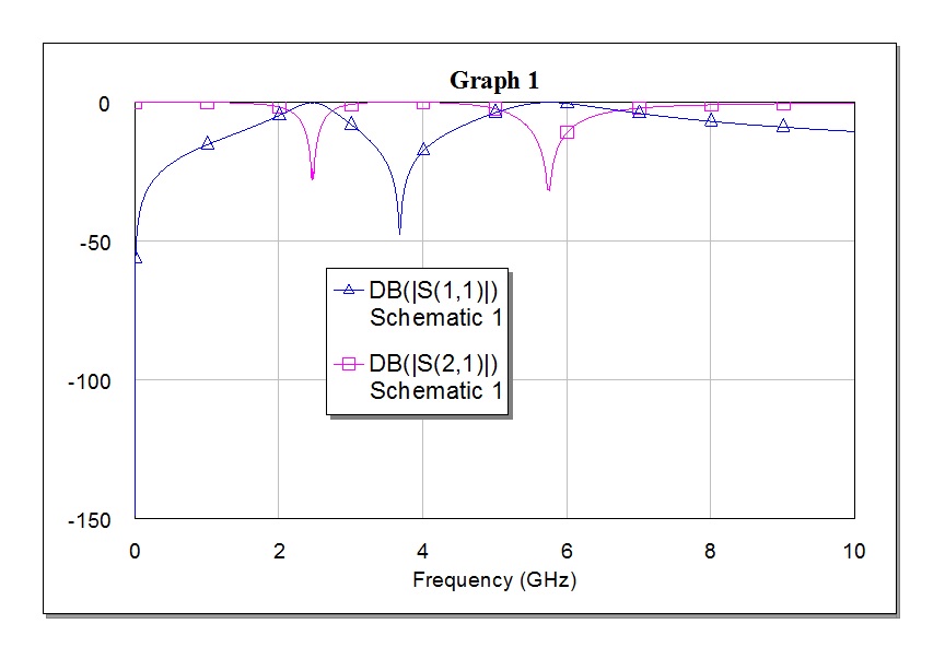
The S-parameters for a DGS band-stop filter by EM simulation in shown in the figure below.
The band-stop model can be easily extracted by parallel RLCs. The figure attached below shows the equivalent RLC circuit model with its frequency response.
But the S11 poles or reflection zeros are not reflected in the equivalent circuit extraction. How to fit the first 4 reflection zeros in the response of the extracted model? How can I achieve this?
Regards
cannibol
Is the modeling correct? What more do I add to achieve a perfect response? Also, how to extract the lumped elements (R,L,G,C) for the microstrip transmission lines?
I am attaching the schematic for the circuit;
The S-parameters for a DGS band-stop filter by EM simulation in shown in the figure below.

The band-stop model can be easily extracted by parallel RLCs. The figure attached below shows the equivalent RLC circuit model with its frequency response.

But the S11 poles or reflection zeros are not reflected in the equivalent circuit extraction. How to fit the first 4 reflection zeros in the response of the extracted model? How can I achieve this?
Regards
cannibol
Your results contradict "can be easily extracted by parallel RLCs".
Obviously, the equivalent circuit is only partly equivalent. That isn't actually surprising when you model a distributed filter with a lumped circuit.
I would expect that you need shunt elements also, at least some shunt capacitance.
After adding transmission lines to represent interaction between DGSs, and after a bit of optimization for its length and width, i am obtaining a frequency response as shown below:
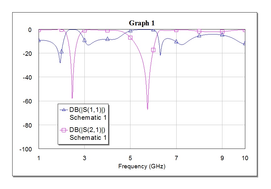

Is the modeling correct? What more do I add to achieve a perfect response? Also, how to extract the lumped elements (R,L,G,C) for the microstrip transmission lines?
I am attaching the schematic for the circuit;
band RLC Extracting 相关文章: