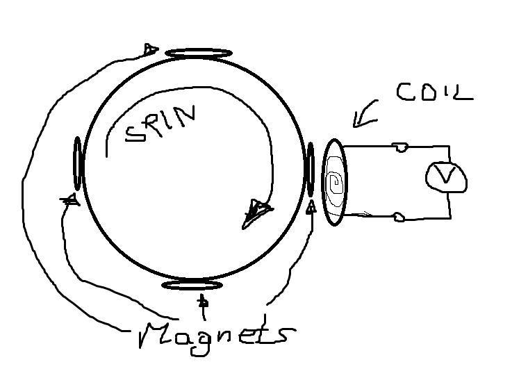
Electromagnetic energy (magnet + coil)

Yes, as the magnetic field running through the coil changes.
V = n*A*dB/dt with A = coil cross section, n number of turns, B induction
So every of 4 magnets will generate voltage pulse? Want to charge capacitor with similar system and send pulse with RF every time, when there are enought energy. Would be perfect to send pulse every 1 full rotation.
Yes. There will be a bipolar pulse for each field maximum. The generated power of the "generator" with open magnetical path will be however low.
It is possible to get >100mV from small magnets and one coil ?
The coil will work a lot better if it has a iron core.
The system will work much better if the gap between the rotating magnets and the coil is VERY small.
The brushless DC motors for my radio control model airplanes have 10 (for one motor) and 14 (for another motor) magnets rotating and 12 fixed coils with iron cores. The gap is extremely small. I can feel the magnets pulling on the coil cores as I turn it. I connected a 1.8V red LED to every combination of its 3 connection wires and rotated the motor fairly fast but the LED did not glow.
I think your "generator" is very crude with only one coil and no iron core.
How did you connected your coils ? Can you show your project ? :)
I did not make my motor, it was made by an electric motor manufacturer. If you look at Brushless Motor Schematic in Google Images then you will see hundreds of drawings of how the coils are wired and most are the same.

As FVM indicated V = n*A*dB/dt with A = coil cross section, n number of turns, B induction
So you will need to factor gap loss and number of turns to generate 100mV or 1V or 10V
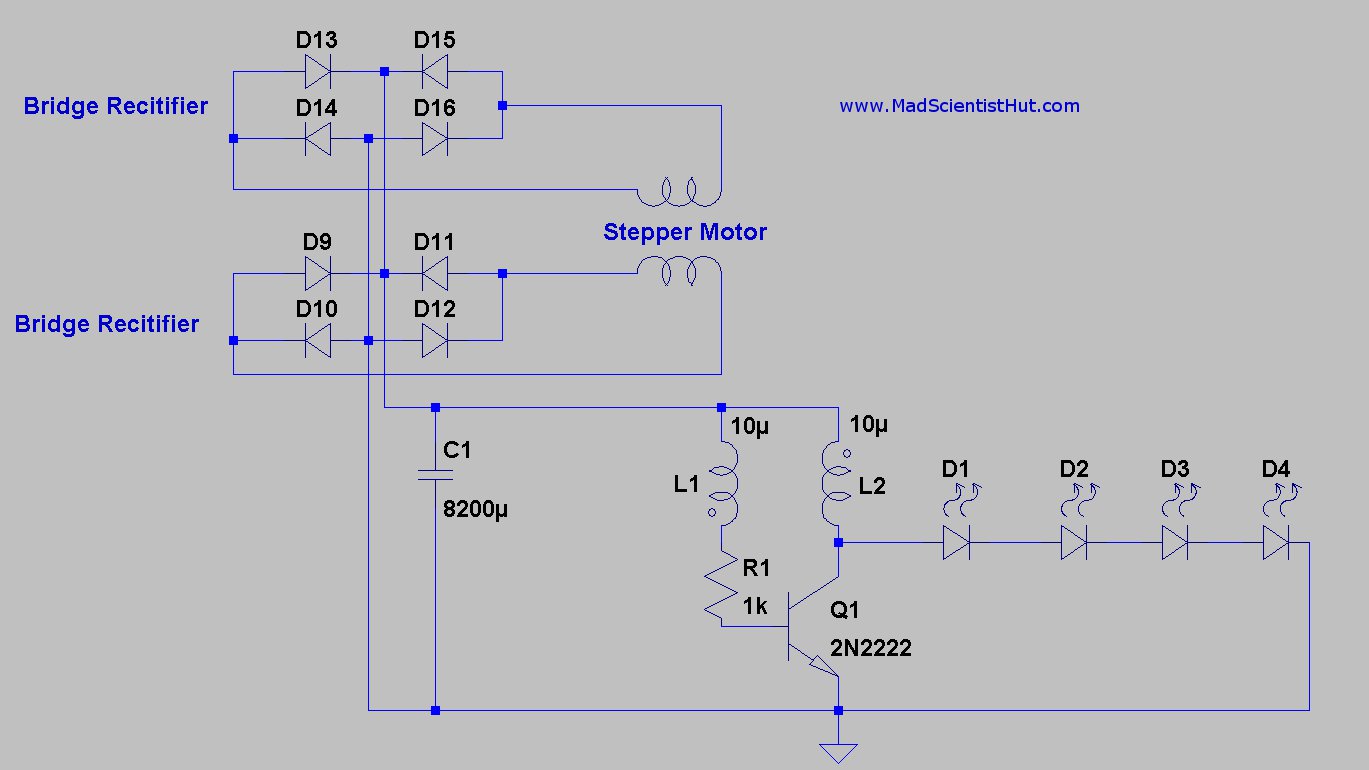
This circuit above converts the higher current at low voltage to higher voltage at low current required to drive a string of LEDs with a few mA at low RPM using a small stepper motor. which use powerful magnets, small gap and many turns.
Maybe someone know with who can and simulate real magnetic field, depending on magnets positions and volgage, caused by rotation of coils ? I need at first step to create construction and to find size and step between magnets, find proper coil sizes and turns, and theorically calculate output. Then i want do same with real components.
Your requirements are vague.
https://www.youtube.com/watch?v=JFSTHTE5VZE
Hi all! Doing stuff, where i need to harvest energy from rotation. So there will be neodynium n52 magnets in a circle, and one coil. With which software can I simulate that system and see what voltage will i have depending on magnets step, rotation sted, coil turns etc. ? Please help :) Thanks !
Harvest energy from rotation?
You remind me about another member on this forum who used a computer fan as a windmill generator to charge a battery that he used at night to light lights on his bicycle. It did not work because the fan was much too small.
He found that when he used a huge fan then it worked. Also he found that riding his bicycle pushing that huge fan into the air was hard work. He was not harvesting energy, instead he was creating energy.
It's a 3D AC magnetics problem that can't be easily simulated. It can be handled by tools like Ansys Maxwell. I'm not sure if suitable free simulation tools exist. If it's the case, you should calculate several weeks of initial learning curve.
It's probably faster to make an experimental setup to get a rough idea of expectable voltage output.
It has been already mentioned that the voltage and particularly the achievable power output will be low without a closed magnetical path of ferromagnetical material. It shouldn't be a problem to get 100 mV with respective number of turns, but what's the intended power output?
Hi all ! I have an idea. I want to do autonomous system , that only transmit signal with RF when there is rotation. I want to find best mechanical construction and to see expected voltage and current at the end of coil. In system are few rotating magnets and one coil (after that power management circuit, supercapacitor etc..) .3D sketch with solidworks is attached . I found that comsol and maxwell are suitable programs for that job, but i do not have knowledge about it. Waiting for help, thanks !
Using a dynamo or alternator with magnets is one idea but magnet or coil weight and size limit its use. The easier way to indicate rotation of a shaft is to put a sticker with black/white bars on the shaft,and use a reflected-light sensor to detect movement/rotation. Then translate sensor output to a RF signal if needed.
Hi jiripolivka, thanks for the answer ! The idea is as I said - autonomous sensor. When the rotation exist, capacitor is charging. When the proper level is reached then RF signal should be transmitted. And depending on rotation speed , I should received signals from RF module. NO BATTERY :) And i want to simulate magnetic field etc. for best construction selection.
To start with a simple thing. The coil must be positioned to receive maximal flux change when the magnet poles pass it. Obviously that's not the case in the image shown in post #15. If you make a nice drawing like this, you should at least show a reasonable coil geometry, isn't it?
There's no doubt that you get some induced voltage, if it's sufficient to supply a RF transmitter has to be analyzed in detail. The previous suggestions to create a closed magnetical path for better energy harvesting are still valid, I believe.
Generally, do you expect to design the magnetical circuit without basic knowledge of electromagnetic theory? This will hardly work.
I'm student of electronic's engeenering (so i have only basics with electromagnetics), and my final work is "Energy harvesting" . I'm working in a company that pruduces RUBBEE (please see at google) . There are one problem, that rubbe should work when pedals are moving. So it will be perfect try to make autonomous "green" wireless system for rubbee..
Check any commercial DC motor, dynamo or alternator. For >100 years,designers have solved all problems you only start to think about...
Without knowing nothing, you seem to try to reinvent the basics.
Best of all, forget simulations and try to make your device by your hands.
I tried this approach at the age of 6, and needed no more simulations.
energy Electromagnetic coil 相关文章:
- Problem with energy in CST for 24 GHz dual reflector antenna.
- FREE electromagnetic simulators, rather than commercial ones
- Re: FREE electromagnetic simulators, rather than commercial ones
- electromagnetic emission from local and global grid
- Need references about numerical electromagnetic !
- Electromagnetic Field Vs Waves
