Understanding the S21
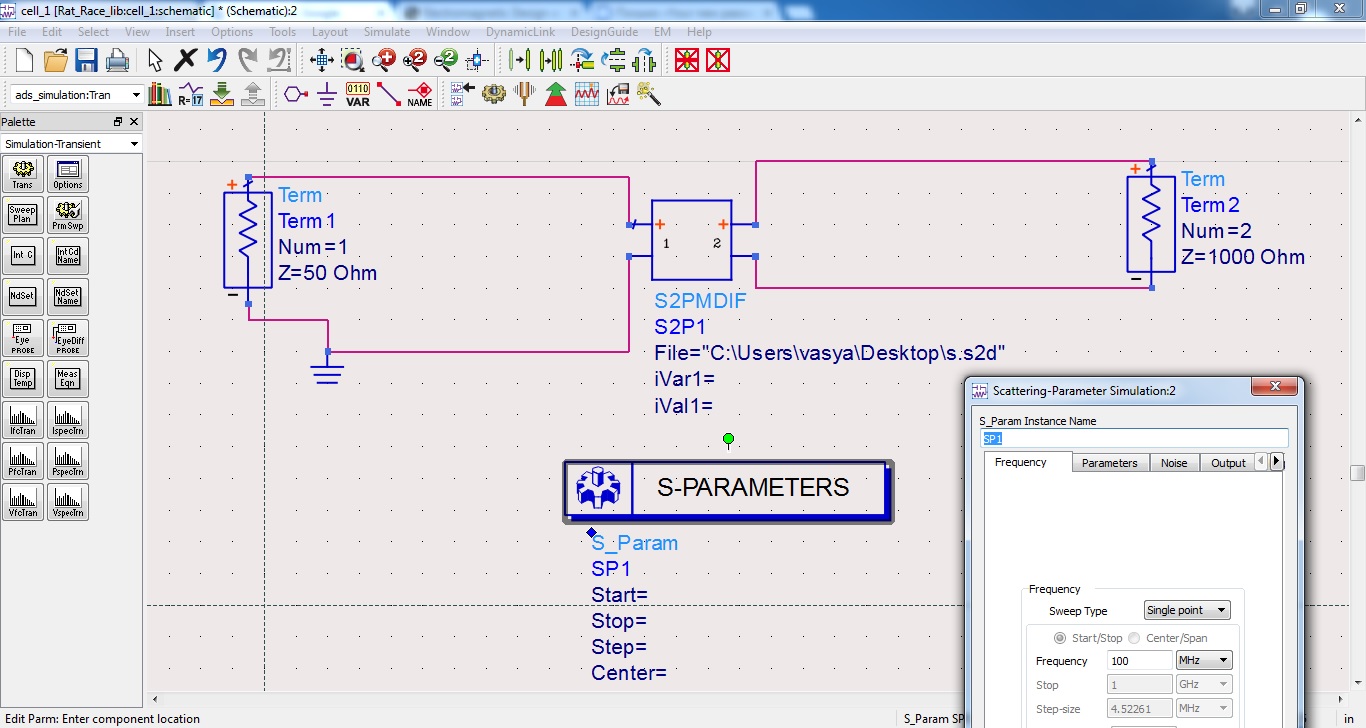
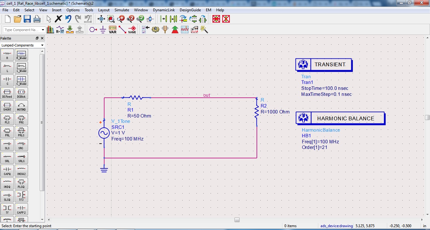
- chip with an input impedance of 1000 ohms (at 100 MHz)
- microstrip line on PCB, and its S-parameters in ***.S2D file
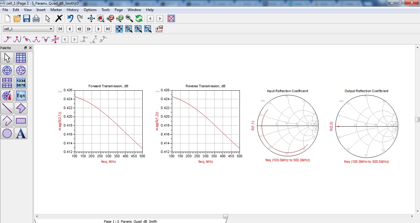
why? simulation in ADS gives mag(S21) = 0.424 (and not seek to 1)
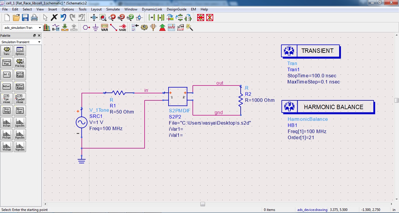
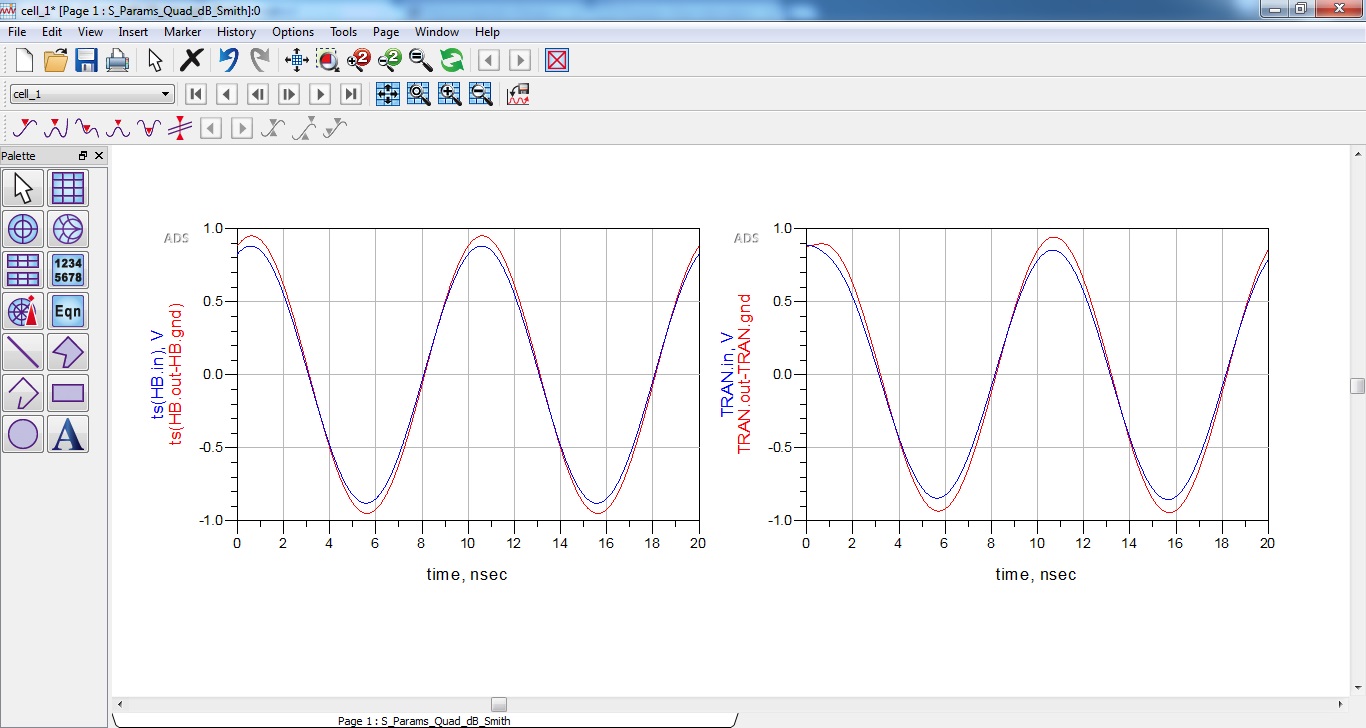
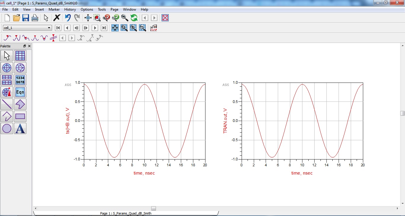
for example, harmonic balance and transient analysis give results, in which no reflections...
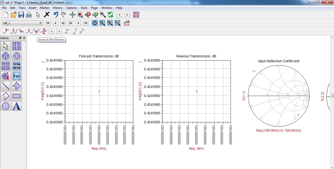
You could try to simulate the S parameter over a frequency sweep. It would be easier when the S parameter is shown over a frequency sweep.
In the first figure, there are no start and stop frequencys set.
please, look:
What result do you expect?
It's hard to tell from your pictures since the microstrip line is not known.
Thank you for helping.. I don't understand why the S21 = 0.425, even if just connect two TERM
Z1 = 50 ohms and Z2 = 1000 ohms..


you expect S21 to be bad S21 =0, correct? i think its due to miss match losses between 50ohm and 1000ohm is not so high!
I want understand how to calculate V2 on TERM2(Z2=1000 ohms) if S21 = 0.425 ?
for example, HB and transient analysis give results, in which NO reflections(HB_TR_sim2.jpg HB_TR_sim_res2.jpg see above)
and V2 = 0.952 -> This is understandable and it's true.. (1*[1000/1050]=0.952)
on the other side S21 = V2/V1.. why = 0.425 ?
I don`t understand=((
ps Thank you for helping..