[moved] [HFSS Newbie Help] HFSS Model and Results Check.
The following is my model:
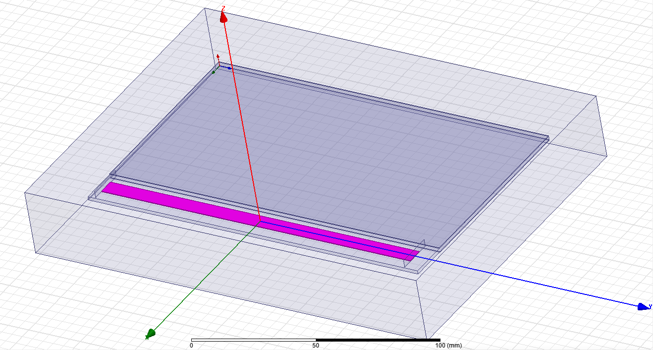
As you can see the outside large cube is the air-filled cavity, and I set it as Radiation Boundary.
The pink part is the 0.3mm thickness atenna, and I set it as Copper and Perfect E.
The thin cube right above the atenna is just copper with 0.3mm thickness, and I set it as Perfect E.
The little bit larger thin cube right under the atenna and the copper is the FR4_epoxy with 1.6mm thickness.
There is also another copper with 0.3mm thickness, and I set it as Perfect E.
There are two lumped port on the two sides of the atenna.
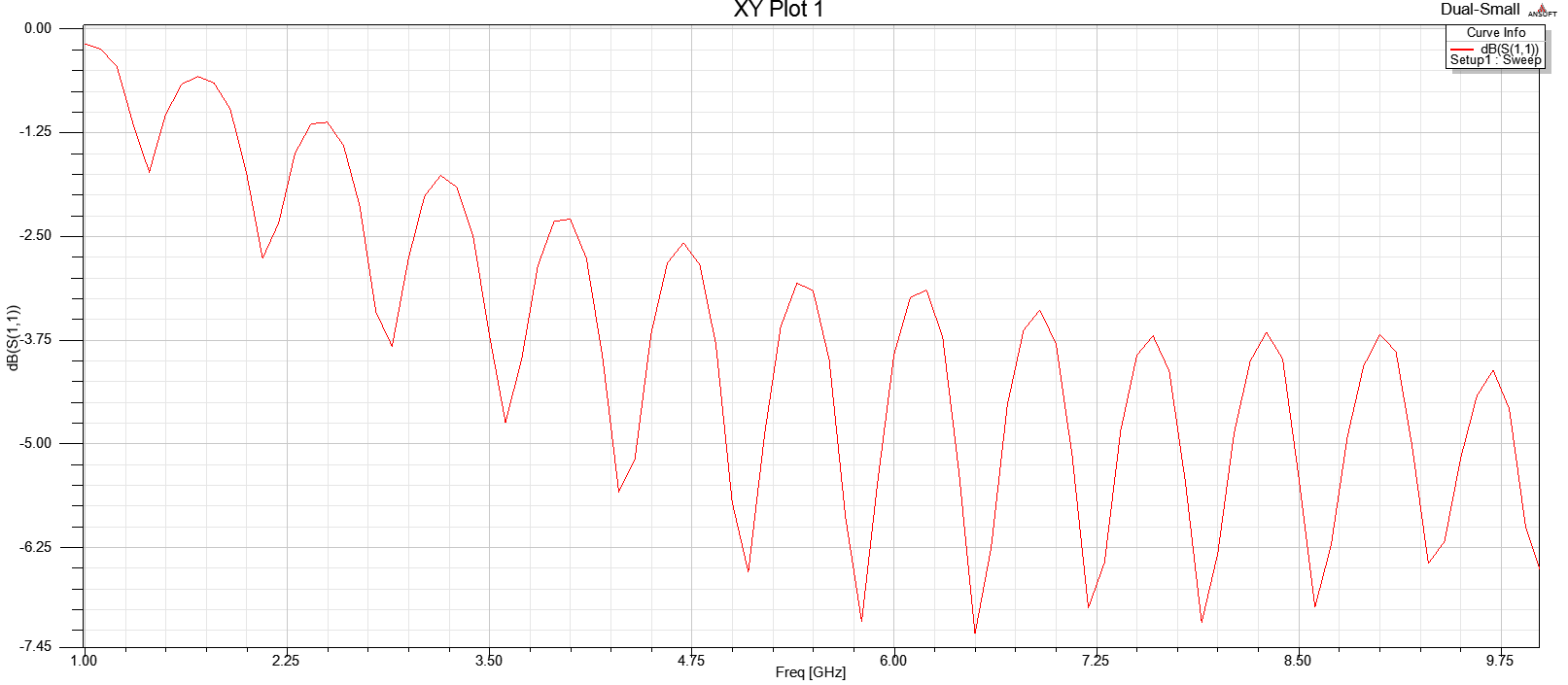
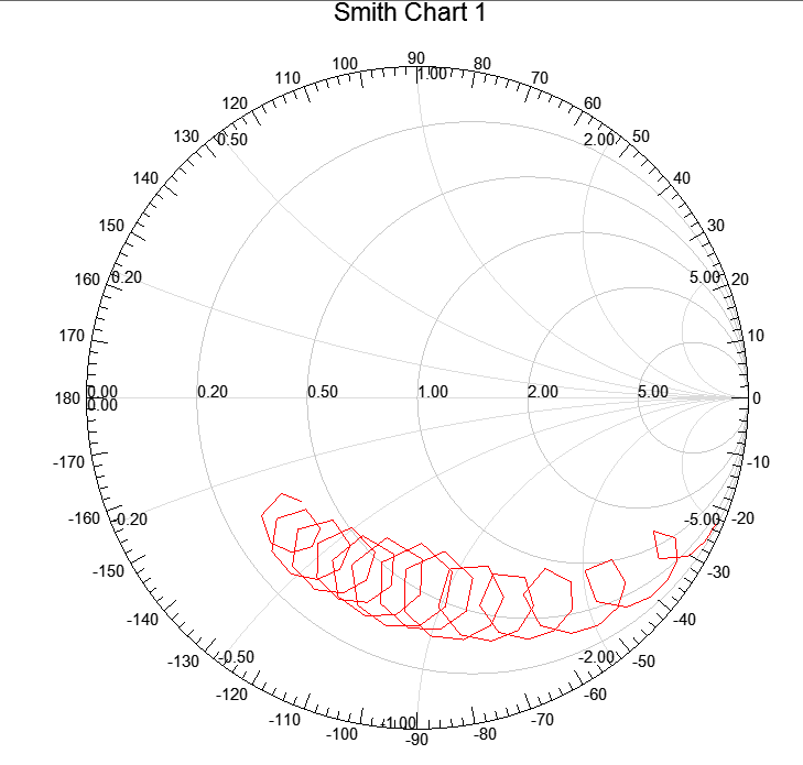
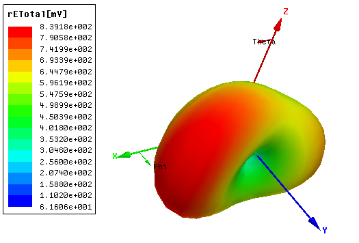
By runing this model, I got some results as followingg:
#1 XY_Plot_S(1,1)
#2 Radiation_Pattern

#3 Smith_Chart
#4 3D_Polar_Plot
I am not sure if my model and my results are right and make sence. Is there any suggestion or tip?
I also have some questions as following:
Q1: Should I use two lumped ports? If there is actually only 1 port connect my antena on the matter. I thought I need to set at least two ports as input and output.
Q2: Should I draw additional rectangles as the plane of ports? Or I can simply use the side face of my antena as the port? If I need draw the additional rectangle as the plane of ports, what is the right size of the plane?
Hope I can have some helps from here[ Or you can just reply your suggestions here.
Welcome thatyang,
A few questions and comments: what kind of antenna is this supposed to be? What type of mode are you trying to excite it with?
If you set a material to copper, you should NOT also be assigning it a PEC boundary.
The radiation boundary should be at least one-quarter wavelength away from any edge of the antenna.
Thanks Plannar.
1. The antenna is just normal 0.3mm Copper on PCB with 1 port as input.
2. I am using Driven Modal as my soultion type, is it what you asking for the type of mode?
3. The radiation boundary should be at least one-quarter wavelength is a good point, it need to increase to at least 16 cm as my calculation.
What type of antenna are you trying to create? Alternatively, what is its radiation mechanism?
No. What mode are you planning on driving with your Driven Modal waveport?
If you don't know with absolute certainty what the answer to my questions are, you need to study more electromagnetic theory before attempting simulations. You won't get very far without it.
Hi Planner, I am not familiar with antenna, and this is my first elecrromagnetic project.
I am not really understand what you are asking for, is there any options for me to choose for the type of antenna and mode?
Thank you so much!
The center frequency is 433.9MHz, and it is using in Toy remote control system.
Also, this is Monopole Antenna, and only for receieving data.
Yes. Google "antennas" for more options.
OK, so it's supposed to be a monopole. Are there two ports attached to the ends of the antenna in post #1? Antennas are typically single-port devices.
This is Microstrip (Patch) Antennas
Yes, it is monopole. However, I saw someone's example that using two ports. This is confused, since the extra ports may just pretend, like 1 port for input and 1 for output? Also, when I using single port, the simulated 3D_Polar_Plot looks weird.
Thanks for your help!
It cannot be both. Which is it?
The "output" of a resonant antenna is its radiation. If the one port response is not giving you the correct result, then either your antenna has beed designed incorrectly, or the port is exciting the wrong mode.
Hence, it is critical to know both what type of antenna it is and what mode you are using to excite it.
Thanks for your help.
I will change it with 1 port:)
This is The monopole antennas in Microstrip Antennas, and I am using lump port with the Integration Line from bottom to top.