CST Studio Suite Farfield Result information interpreting
时间:03-30
整理:3721RD
点击:
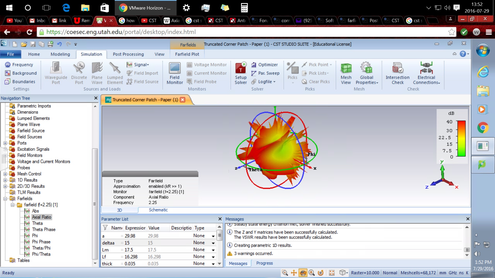
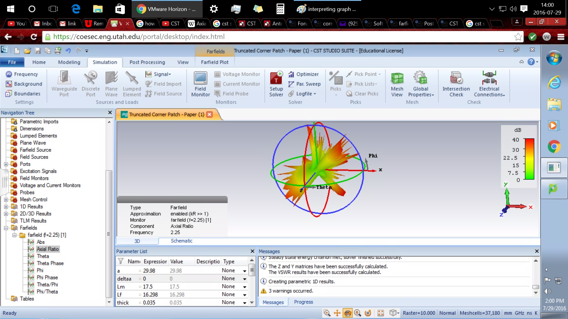
I'm running simulations for an antenna patch, and i'm trying to understand the farfield 3d information that shows from green to red with numerical values assigned to this a side bar showing green to red. I remember that the more red the numerical value, the more round the corner of a square antenna patch physically has, but that's the extent of my memory. Could there be more drawn from what i'm seeing?
This patch "delta a" as in the corners of the antenna patch rounded out significantly. "delta a" = 15
This patch "delta a" as in the corners of the antenna patch rounded out significantly. "delta a" = 5
This patch "delta a" as in the corners of the antenna patch rounded out significantly. "delta a" = 0
Also, could each of the farfield graphing option be simply be explained to me please?

This patch "delta a" as in the corners of the antenna patch rounded out significantly. "delta a" = 15

This patch "delta a" as in the corners of the antenna patch rounded out significantly. "delta a" = 5

This patch "delta a" as in the corners of the antenna patch rounded out significantly. "delta a" = 0
Also, could each of the farfield graphing option be simply be explained to me please?
- Syntax for rectenna efficiency using Qucsstudio
- Simulation of nanoantenna in CST Studio
- Looking surface current at which port out of many in cst microwave studio
- CST Studio Body size outside of dynamic range of 3D modeler
- [CST Microwave Studio] Liguid material simulations
- [CST Microwave Studio] Modified capacitor structure
