implement Lumped RLC series or parallel elements in HFSS
时间:03-30
整理:3721RD
点击:
While designing Lumped RLC boundaries between two microstrip patch line, we design a face between two lines and then apply RLC boundaries to that face.
What will be the face dimension? is this will affect the result?
How can we know it is series RLC or parallel RLC or mixed (R series with parallel L C)?
Any video or document may also help, if any.
Any correction in question are also welcome.
Thank you
So what dimension of face should be taken, I mean some mathematical relation is there.
Kindly help.
thank you.
What will be the face dimension? is this will affect the result?
How can we know it is series RLC or parallel RLC or mixed (R series with parallel L C)?
Any video or document may also help, if any.
Any correction in question are also welcome.
Thank you
Whatever you set it to.
Yes, unfortunately. I don't think there's a way around this. If it's electrically small, and the values relatively large, then the size doesn't appear to make *much* of an impact.
The three components are in parallel.
See the HFSS help documents for further details.
PlanarMetamaterials Sir
Does this mean RLC are always parallel by RLC boundary conditions in HFSS?
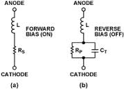
To implement PIN diode, should we implement two cases , one for forward bias and one for reverse bias.
So what dimension of face should be taken, I mean some mathematical relation is there.
Kindly help.
thank you.
Yes. You can obviously cascade multiple R, L, or Cs to get series components.
Sounds right.
I'm sure if you really need to know, you could figure it out from the field formulations. See the HFSS documentation for more details.