Varactor power consumption
I am working on the calculation of the power consumption of a varactor diode.
Is the power consumption rated to the reverse leakage current when the varactor is correctly biased?
Thank you for the help in advance.
I have never seen a power spec for a variable cap. diode, because the dissipation is irrelevant.
If there was one, it would apply in the forward conduction mode.
Varicaps are usually tested for Vr min at 1uA. which must be above the rated voltage.
Varactors are also used for frequency multiplication, in which case the forward current and recovery time both incur power loss. To be honest, I have no idea how to calculate the consumption but I would imagine it to be much like a fast Schottky diode calculation, a combination of (I * Vf) during conduction and some extra for losses while it conducts during recovery. The exact amount would depend on the frequency and applied voltage.
Varicap (variable capacitance) diodes are a kind of varactor but always used in reverse bias mode to keep the depletion region insulating so the current will be very small as Tony points out.
Brian.
Hi, normally there is a Power dissipation parameter provided by the manufacturer. For example, SKYWORKS SMVA1248-079LF, the maximum Power dissipation is 250 mV.
So no one cares the power consumption of a varactor? What if I use a large number of varactors with high voltages? Still no obvious power consumed?
I do not understand your question. Now you have told us the type number we can see it is a tuning varactor, not the kind used for frequency multiplication.
The maximum dissipation is quoted as 250mW but that assumes it is being forward biased. Under normal circumstances it would be reverse biased and the current through it would be a few nA with virtually zero power dissipation.
Why are you suggesting several are used with 'high voltages', the maximum for that device (Vr) is only 15V.
What is your application?
Brian.
Hi Brian, Thanks a lot for your reply. I understand better. I have another question.
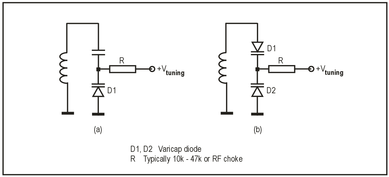
To bias a single varactor in the flowing figure (a), what is the function for the capacitor?
I cannot get it as a DC blocker.
For dual control , mirror R,C,D parts from right to left side and duplicate with L inbetween , instead of grounded for differential Pi filter.
Why you want so much tuning range?
To work for tuning you rely on the capacitance changing as the voltage across the diode is changed. Inside all diodes (excluding some exotic types!) there is an area around the PN junction where electron/hole mobility produces a 'depletion region', it's a kind of no-mans land where the charges in the P material and N material balance each other. When you forward bias a diode, the 'push' from an externally applied voltage has to overcome the depletion barrier and force electrons to flow across it. When you reverse bias a diode, the opposite happens, the barrier gets wider. A varactor is like an ordinary diode but has the P and N doped areas specailly constructed so the width of the barrier can be accurately controlled. Because both the P doped part and the N doped parts are conductors they work like the plates of a capacitor and the depletion region is like the insulating dielectric between them. As you change the reverse voltage and alter the barrier width, it's like moving the platesof the capacitor closer of further apart so it's value changes.
Looking specifically at your schematics, they both meet the criteria for tuning the LC circuit (L is the coil, C is the varactor capacitance), there is a DC path across the diode and an AC path for the signal.
The left image needs a series capacitor or the low resistance of the coils will short out the DC. The capacitor would typically be larger than the varactor capacitance so the varactor makes a proportionately large change in overall capacitance across the coil. Note that the tuning voltage is positive and the diode is therefore reverse biased.
The right image does not need the capacitor because the second varactor is also reverse biased, it gets it's DC return through the coil. So both diodes have the same voltage across them and they appear to be in series giving half the overall capacitance of a single diode.
In both cases, the resistor is there to isolate the voltage source from the tuned circuit. Because the diodes are not conducting (except for tiny leakage current) there is no voltage drop across the resistor.
If you wanted more capacitance variation, you would use two varactors in parallel.
Brian.