Re: How to correctly calculate coil's field strength?
That is what i decided already, thankfully i have a gaussmeter, my PS should arrive soon. Tests will show what is the optimal configuration.
This was the first mention you made of the spiral geometry so far.
Let's agree, this thread seems like not converging to anywhere.
Bring us results of your experiments, as well as drawings of the actual apparatus you are measuring.
To get an idea of possible coil geometries, see the field of a cylindrical coil with 400 turns of 1mm wire. Due to the axisymmetric simulation setup, only the upper halve is shown.
It's quite obvious that you have difficulties to pack the turns into a compact coil. Neither a flat nor a single layer can do.
What else would a flat coil be but a spiral, it's certainly not a circle. It's a shame how people often don't see the forest for the trees. I'll proceed with research and experiments on my own, all the best to everyone here.
A few conclusions from the previously posted simulation:
- Although expectable, I didn't see clearly before that for a rotational symmetrical geometry, the minimum field strength always occurs on the center line. And for a single coil configuration (unlike e.g. Helmholtz coil) on the outer points, in other words the minimal field strength points are r=0, z=+/- d/2. This simplifies calculation of optimal coil geometries a lot. Everything boils down to summing up the field of single turns, given as

- The simulation uses the previously assumed current of 20A through 1 mm wire, corresponding to a current density of about 25A/mm2. The current level isn't feasible for continuous operation unless you implement special cooling methods, liquid cooling or at least molding the winding in a material with high thermal conductivity and bringing it in contact with a large heat sink.
- The simulation didn't even achieve half of the intended 0.4T flux, either the current or the winding volume must be further increased.
- You can play around with coil length, diameter and number of turns and find the optimal geometry for a given wire length. As far as I see, the performance curve is rather smooth.
Doesn't sound promising at all.
I want to clear one important detail up.
DO OUTER WINDINGS OF A PANCAKE COIL CONTRIBUTE LESS TO THE FIELD IN THE CENTER OR NOT?
If we look at the formula for a field of a single loop we can see flux gets weaker with bigger radius.
B = u0 x I / 2R
But isn't it logical flux from outer windings must also pass through the center? Where else would it pass?
I mean no matter how wide we make the "pancake" those most outerwinding will still converge through the central gap and thus increase the central flux just as much.
OR?
The answer is of course yes it is less to your 'shouted' question.
Field strength is prop. to radius i. e. distance... 2πr
Field density is inverse prop to area or .. πr^2
So for a larger loop, field density (tesla's) at centre is prop. to 1/r
Why is this hard to understand?
You obviously did not understand the question.
Of course flux gets lesser with increasing radius for a single loop,
same amount of field lines spread out over larger volume.
I am asking for a pancake coil, not a single loop.
Are we to assume that field lines produced by the outer winding will not pass through the center? This certainly makes no sense.
And if they pass through the center they should contribute the same as the inner coils.
(Same answer)
You may be confusing between total flux, and flux density. Tesla is a unit of flux density
I'm surely not confusing flux with flux density and i know the unit and how it's calculated
That is exactly what i pointed at, that despite flux density being less for single loop of bigger radius, when that loop is part of a pancake coil where else would it's lines of force pass but through the center of the coil.
If they do, and they do, it is clear outer loops should contribute just as much to center field density as inner do.
If you disagree explain it in scientific terms or don't waste valuable server resources.
I admit to have wrongly used the term flux for flux density B in some places.
The difference is relevant in so far that the ampere-turns generate the flux which doesn't depend on the radius of the ring current, but the flux density in the center does.
Your question has been clearly answered, the outer pancake coil windings contribute less to the center flux density, so do the outer windings of long coil. That's the reason why the optimal coil geometry is neither pancake nor long single layer but some kind of cylinder as previously stated.
I guess it is so, i previously heard a kind of rule never wind above the core thickness.
But logically speaking, i still don't get it why would outer loops contribute less flux to the center if their flux lines all converge to the center just like those of inner coils.
Are we to assume outer coils not only contribute less to flux density in the center but also produce less flux in the first place?
Or part of their lines doesn't pass through the center but loop before reaching it?
There must be a logical answer. But yea, like i already figured, neither pancake nor long solenoid seem to be the best solution but optimal compromise between the two.
Also i would very much appreciate if someone tries the Tesla bifilar config vs ordinary solenoid. Many people claim stronger field, while others claim no difference.
We need to clear that up.
ANYONE TRIED TESLA BIFILAR?
"... part of their lines doesn't pass through the center but loop before reaching it?... " Is correct, and simplest way to explain to you.
Why do you assume all the flux "rushes" to the exact center? Flux is highest near the current flow and decreases with distance away.
This thread is now a waste of time, and I for one am exiting.
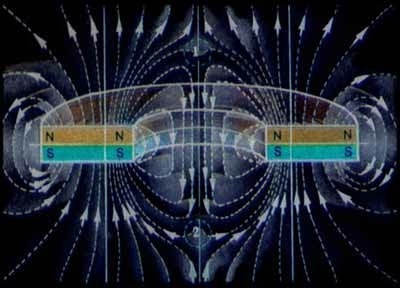
You obviously have no understanding of how fluxlines form around a central gap. I attach an illustration so you get a basic picture.

Thread is surely not waste of time, your contributions to it surely are.
This drawing does not represent a simple coils' (whether planar, spiral, cylindrical) magnetic field lines. It is clearly a pictorial of some other configuration/ other device.
Since you are basing most of your theories on this pictorial, it would be useful for this forum to know where it is obtained from and what does it refer to ?
It's obviously shows a permanent ring magnet, not coils, but it nicely shows the distribution of flux through the center.
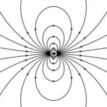
Here's another pictorial which nicely shows flux distribution over a surface, and which also does not have anything to do with your original questions
Here's another one showing something else..

enjoy !
The ring magnet field picture is expressing much artistic freedom, less exact calculation, I think. There's no way to bend the field lines like the drawing suggests.
The simulation shown in post #23 is giving a more realistic view of expectable flux density.
You shouldn't hold your illustration against well known physical facts like this
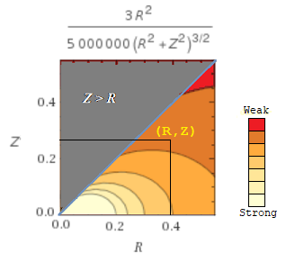
As mentioned before, a numerical simulation with graphical views could be more insightful than any analytical or intuitive method. When the formula for the magnetic field inside of a flat ("pankake") shape is computed, adding arbitrary values for the parameters N and R and I, it is noticed that the field in the center is always minimum. Note the color of the pattern below bleached along the vertical cursor from the coordinate (R, Z) downto (R, 0):

Regardless of the electric current value, since there is no saturation of the magnetic field in the air, the contribution of variable I in the formula is linear, and doesn't matter whether the B field is weak or strong, it exhibits a change rate always decreasing the field magnitude toward the center of the ring. In short, don't matter how weak is the magnetic flux, it will always be stronger close to the wire.
Note that the above analysis was based on a formula which is in itself a simplification of the most general case, moreover some stuffs were added by hand therefore not being a precise chart.
Therefore in order to get a more accurate result I would recommend you make simulations with field solver tools (there are freeware options), in order to get a more realistic view, adding the actual 3D geometries, e.g wire gauge, material permissivity, etc...
Are you now saying field is weakest at the center of the solenoid. I assume you mean since it is the farthest point from the coils looking inward. Or is there something i'm missing.
calculate correctly coil 相关文章:
- How to correctly calculate coil's field strength?
- How to calculate radiation from pcb edge with magnetic current ?
- HFSS: Calculate Electric Field Inside the Substrate
- Calculate the raduis of circulair patch antenna
- Calculate input impedance with caviy model
- How to Calculate Transmission line feed Length,width and gap for a rectangular patch
