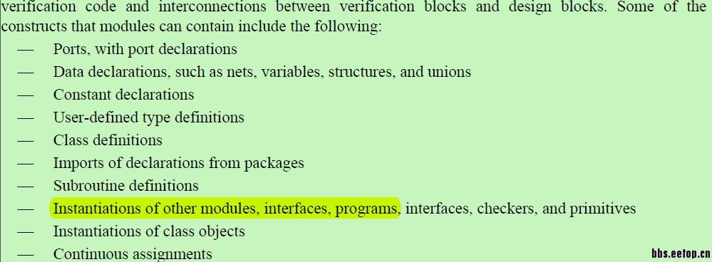
systemverilog在module中例化program的问题
 现在有个疑问:如下例:
想法很简单:
一个设计模块module adder,加法器,两个输入a和b,一个输出o。
一个验证模块program p,一个输入i(对应设计模块的输出),两个输出x和y(分别对应设计模块的a和b)。
一个tb模块,将设计模块和验证模块连接起来。
实现:类随机变量随机化值送给设计模块,设计模块执行后的结果由类中的任务打印输出。
module adder(a,b,o);
input bit [1:0] a;
input bit [1:0] b;
output bit [2:0]o;
always@(*)
begin
o = a + b;
end
endmodule
program p(input bit [2:0] i, output [1:0]x, output [1:0]y);
class c;
rand bit [1:0] m;
rand bit [1:0] n;
task display();
$display("the value of a is %2b!", m);
$display("the value of b is %2b!", n);
$display("the value of result is %3b!", i);
endtask:display
endclass:c
c c0;
initial
begin
c0 = new;
c0.randomize();
c0.display;
end
endprogram:p
module tb;
wire [1:0]a;
wire [1:0]b;
wire [2:0]o;
addr a0(
.a(a),
.b(b),
.o(o)
);
p p0(
.x(a),
.y(b),
.i(o)
);
endmodule
编译执行结果:
the value of a is10!
the value of b is 01!
the value of result is 000!
只执行了program部分程序,adder模块和tb模块根本没起作用,想问一下,如果想实现我说的功能,应该如何改进?
谢谢
把设计模块adder去掉,只保留验证模块和tb模块,通过tb模块直接初始化的方式向验证模块中传值,编译和运行都有正确的结果的。设计模块为什么不行呢?是因为他们运行同时运行的原因吗?
program p(input bit [2:0] i, input [1:0]x, input [1:0]y);
class c;
task display();
$display("the value of a is %2b!", x);
$display("the value of b is %2b!", y);
$display("the value of result is %3b!", i);
endtask:display
endclass:c
c c0;
initial
begin
c0 = new;
c0.display;
end
endprogram:p
module tb;
logic [1:0]a;
logic [1:0]b;
logic [2:0]o;
p p0(
.x(a),
.y(b),
.i(o)
);
initial
begin
a = 2'b01;
b = 2'b10;
o= a + b;
end
endmodule:tb
编译执行结果:
the value of a is01!
the value of b is 10!
the value of result is 011!
第一个里面加个延时试一下。
initial
begin
c0 = new;
c0.randomize();
#1ns;
c0.display;
end
不对。我试一下虚拟接口看看
对的,它们确实不是在同一个area里面执行的。module的执行要比tb早,而且你这里没有时间点的概念,相当于tb执行了一次,那在同一时刻tb就晚于module,所以module采样不到变化,就不会触发always进程语句。你可以试试加入时钟周期到module和tb中,你会看到,第一拍tb产生a和b以后,第二拍module才会根据上一拍的a和b计算,大概是这个意思。用vif估计也不行。你可以试试我说的。
仔细看了一下,testbench不对,往class里面传递参数可以使用new函数,当然要改的地方还有几个,好好修改一下吧
采用virtual后的程序改为如下:
//定义接口
interface itf;
logic [1:0]a;
logic [1:0]b;
logic [2:0]o;
modport DUT(
input a,b,
output o
);
modport PM(
input o,
output a,b
);
endinterface:itf;
//module adder(a,b,o);
module adder(itf itf0);
//input bit [1:0] a;
//input bit [1:0] b;
//output bit [2:0]o;
always@(*)
begin
//o = a + b;
itf0.o = itf0.a + itf0.b;
end
endmodule
//program p(input bit [2:0] i, output [1:0]x, output [1:0]y);
program p(itf itf0);
class c;
rand bit [1:0] m;
rand bit [1:0] n;
virtual itf vif;
function new(virtual itf itf0);
vif = itf0;
endfunction:new
function value();
vif.a = m;
vif.b = n;
endfunction:value
task display();
$display("the value of a is %2b!", m);
$display("the value of b is %2b!", n);
//$display("the value of result is %3b!", i);
$display("the value of result is %3b!", vif.o);
endtask:display
endclass:c
c c0;
initial
begin
//c0 = new;
c0 = new(itf0);
c0.randomize();
c0.value();
#1;//设计模块为纯组合逻辑的原因,时序逻辑应该是不需要延时的
c0.display();
end
endprogram:p
module tb;
//wire [1:0]a;
//wire [1:0]b;
//wire [2:0]o;
itf itf0();
//addr a0(
//.a(a),
//.b(b),
//.o(o)
//);
adder a0(itf0);
//p p0(
//.x(a),
//.y(b),
//.i(o)
//);
p p0(itf0);
endmodule
编译执行结果:
the value of a is10!
the value of b is 01!
the value of result is 101!
结果还是错误的啊。
程序是编译执行过的,应该是没错的。你可以把你编译的的代码和log信息贴一下
