(纯水)大家有什么想问的?问啥都行。
一直都比较忙,也常常想上来回复一些问题。但是,手残,翻页比较慢。
所以特开此贴,收集并解答各种问题,提供各种咨询和建议。
无论行业内还是行业外,无论技术类还是非技术类,任何问题都可以来讨论和咨询。
本人不才,能解答的将立即作答,无法解答的也请各位坛友帮忙解答。
祝大家新年工作顺利,节节高升!
2015/2/28
Shanghai
谢版大,求证一个问题。ocv在icc guide中有-max -min的设置,这个是不是针对一个corner有两个库设置的,工程中一般一个corner只给一个库。所以用set_timing_derate来模拟两个库 max和min。 另外ocv是不是一般只设置clock上
一般来说,derate会设在clock path上,但是并不能说data path不能设。
Data path上同样可以定义timing derate。但是你的setup或者hold可能会更加难close。
你不仅仅可以这样做,还可以针对cell delay和wire delay分别来定义derate。
你这里可能存在误区。
-max和-min是用在BcWc Analysis mode下,然而当你采用了MMMC,你需要通过-delay_coner来控制。
具体参见下面的例子
Examples
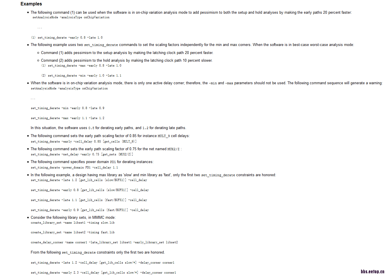
- The following command (1) can be used when the software is in on-chip variation analysis mode to add pessimism to both the setup and hold analyses by making the early paths 20 percent faster:
setAnalysisMode -analysisType onChipVariation
...
(1) set_timing_derate -early 0.8 -late 1.0
- The following example uses two set_timing_derate commands to set the scaling factors independently for the min and max corners. When the software is in best-case worst-case analysis mode:
- Command (1) adds pessimism to the setup analysis by making the latching clock path 20 percent faster.
- Command (2) adds pessimism to the hold analysis by making the latching clock path 10 percent slower.
(1) set_timing_derate -max -early 0.8 -late 1.0
(2) set_timing_derate -min -early 1.0 -late 1.1
- When the software is in on-chip variation analysis mode, there is only one active delay corner; therefore, the-minand -max parameters should not be used. The following command sequence will generate a warning:
setAnalysisMode -analysisType onChipVariation
...
set_timing_derate -min -early 0.8 -late 0.9set_timing_derate -max -early 1.1 -late 1.2
In this situation, the software uses 0.8 for derating early paths, and 1.2 for derating late paths.
- The following command sets the early path scaling factor of 0.85 for instance MULT_9 cell delays:set_timing_derate -early -cell_delay 0.85 [get_cells {MULT_9}]
- The following command sets the early path scaling factor of 0.75 for the net named MUX2/Z :
set_timing_derate -net_delay -early 0.75 [get_nets {MUX2/Z}]
- The following command specifies power domain PD1 for derating instances:
set_timing_derate -power_domain PD1 -cell_delay 1.1
- In the following example, a design having max library as 'slow' and min library as 'fast', only the first two set_timing_derate constraints are honored:
set_timing_derate -late 1.2 [get_lib_cells {slow/BUFX1}] -cell_delay
set_timing_derate -early 0.8 [get_lib_cells {slow/BUFX1}] -cell_delay
set_timing_derate -late 1.1 [get_lib_cells {fast/BUFX1}] -cell_delay
set_timing_derate -early 0.9 [get_lib_cells {fast/BUFX1}] -cell_delay
- Consider the following library sets, in MMMC mode:
create_library_set -name libset1 -timing slow.lib
create_library_set -name libset2 -timing fast.lib
create_delay_corner -name corner1 -late_library_set libset1 -early_library_set libset2
From the following set_timing_derate constraints only the first two are honored.
set_timing_derate -late 1.2 -cell_delay [get_lib_cells slow/*] -delay_corner corner1
set_timing_derate -early 2.3 -cell_delay [get_lib_cells slow/*] -delay_corner corner1
set_timing_derate -late 3.4 -cell_delay [get_lib_cells fast/*] -delay_corner corner1
set_timing_derate -early 4.5 -cell_delay [get_lib_cells fast/*] -delay_corner corner1
我只是个搬运工,希望能帮助你理解。
刚提问个问题就看到这个帖子,那么我把我发的问题在这里重复一遍,谢谢小编答复
为什么ck端设了负的latency会把这只ck path做的更短而不是更长
latency是负值的话,不应该是延长了ck path吗,求指点,谢谢
思路没错,但是信息量不够。我不知道该如何解释。
参考了一篇paper 原文如下5.4 Two Operating conditionsSometimes you may have operating conditions specifically scaled for use with on-chip variationanalysis. For a slow chip analysis, the worst case operating condition is specified with –max andthe scaled worst case operating condition is specified with –min. For a fast chip analysis, the bestcase operating condition is specified with –min and the scaled best case operating condition isspecified with –max.
set_operating_conditions –analysis_type on_chip_variation –min $WCOCV –max $WC
5.4 Single Operating conditionOn-chip variation analysis can still be run even if you have only one operating condition. In thiscase the minimum and maximum times are simply scaled versions of the delays determined fromthe single operating condition that is loaded. The scaling factors are set by the set_timing_deratecommand described next. This is the method that was used for this paper.
set_operating_conditions –analysis_type on_chip_variation $OP_CON
set_timing_derate –min 0.8 –max 1.0
所以我的理解是ocv 和-max -min并不矛盾。前提是一个corner提供了两个库
我这里只是针对软件工具本身,ICC我不清楚,我贴上来的是EDI的Doc。
谢谢版大回复,两个软件ocv的设置不一样。坐等icc 的童鞋
我的理解和你一样
很多做后端的都没搞清楚,也没去想过
也向其他人问过,应该是这么理解的,谢谢回复
DC怎么综合在Quartus2里面调用的IP核?
个人的理解 max/min 针对的是两个库
cadence encounter layout 自动布线下孔偏移,via1偏移导致DRC错误。初步判断是因为建的库的端口METAL1不在软件规定的METAL1通道上,如何关闭这个呢?
这个问题请发到其它板块。
贴一下你的setNanoRouteMode
这里面的:
•Command (1) adds pessimism to the setup analysis by making the latching clock path 20 percent faster.
•Command (2) adds pessimism to the hold analysis by making the latching clock path 10 percent slower.
(1) set_timing_derate -max -early 0.8 -late 1.0
(2) set_timing_derate -min -early 1.0 -late 1.1
我理解的怎么是这两个命令都是作用在capture path上的呢,难道我理解一直都是错误的?
(1)既然是加速,对于setup来讲,early不是应该作用在captrue path上吗
(2)既然是减速,对于hold来讲,late不是应该作用在capture path 上吗
CTS后有些时序机器修不过去怎么办,比如同一个root点出来,in2reg path datapath 到reg 的 D pin 这个D pin是exclude pin 然后这天data path和capture path上的cell 都是fixed的,capture path 的root点也是这个点
use CCOPT,
set_ccopt_property add_exclusion_drivers true
为什么hold是同沿检查?一直只知道这个,却不明白原理
Hold Timing Check
A hold timing check ensures that a flip-flop output value that is changing
does not pass through to a capture flip-flop and overwrite its output before
the flip-flop has had a chance to capture its original value. This check is
based on the hold requirement of a flip-flop. The hold specification of a
flip-flop requires that the data being latched should be held stable for a
specified amount of time after the active edge of the clock.
Just like the setup check, a hold timing check is between the launch flipflop
- the flip-flop that launches the data, and the capture flip-flop - the
flip-flop that captures the data and whose hold time must be satisfied. The
clocks to these two flip-flops can be the same or can be different. The hold
check is from one active edge of the clock in the launch flip-flop to the
same clock edge at the capture flip-flop. Thus, a hold check is independent
of the clock period. The hold check is carried out on each active edge of the
clock of the capture flip-flop.
谢谢!
是不是这么理解:本周期数据到达之前,要采到上一周期送来的数据,也就是第一级寄存器输出的数据在到达第二级寄存器之前,第二级寄存器要采到之前的数据,而第一级输出数据和第二级才到数据是同一个时钟沿,所以是同沿检查。
用abs 抽取的lef 和foundry提供的lef 为啥差别那么大?
它提供的lef 有很多 相对位置关系, 这个抽取的里面很少啊
想通了就行了。
这两条command针对的都是clock path(即capture path),相对应的还有一个capture clock path。
我明白了,EDI里面的说的latching clock path 就是平常大家说的capture path,是说的同一个意思,clock path前面加了个latching确实挺让人迷惑的.EDI的man显然没有ICC的man更让人清晰明了.
本科毕业生做后端设计,工作好找吗?
小编你好,我在做calibre DRC的时候遇到了iofiller上的错误。错误类型是"ME1.slotAdditional { @ If using the wide metal defined as being > 35um,the metal slot must be placed for releasing stress
SIZE NPDME1 BY 17.5 UNDEROVER
}"。意思应该说的是iofiller连成的电源环宽度超过35um(io filler由几段组成,其中的两段长度约为50和70um,连成电源环后,由于长度约为170um,所以filler中的这两段就变成了ME1的宽度),就需要开槽。于是我把图片放大,发现filler上面已经有contact了。难倒contact不算slot吗?
请教下,小项目,数字后端外包给人做,是个不规则的凸字形,规划的是1700umx400um。结果出来,居然插了10%左右的没用的电容。还把宽度拉宽了50。我的问题是这样的利用率是不是太低了。还是形状奇怪,导致没法提高利用率?有什么好办法提高数字版图的利用率?