CC1310 Timer延时不准
在一个项目中,需要做一个精确的延时,因此想到用Timer来做,但是发现,Timer的延时不准确。
目前使用Timer2_A,配置方式是 向下计数的方式,并且做了16分频。
整个程序的流程如下:
1. 当Board_ZD_Input的上升沿来了之后,使能Timer,并且将Borad_RELAY0口置高。当Timer out之后,将Borad_RELAY0口置低
2. 为了防止系统进入idle状态,在ccfg中屏蔽idle任务,并且将.enablePolicy = FALSE,是系统始终处于active状态。
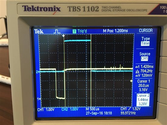
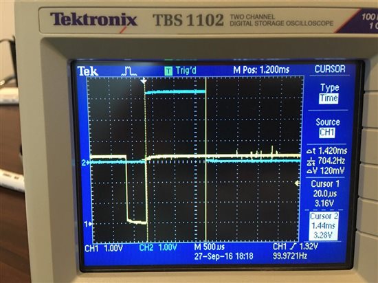
在程序中,我试过TimerLoadSet(GPT2_BASE, TIMER_A, 4000); 和TimerLoadSet(GPT2_BASE, TIMER_A, 8000);, 其延时(测量Borad_RELAY0高电平的时间)分别约为1.42ms和2.82ms,倒着折算出来的主频,大约是45MHz左右,而不是标准的48MHz。请问问题出在哪里?
下面是我的代码,以及示波器的截图。
/***** Includes *****/
#include <stdlib.h>
#include <xdc/std.h>
#include <xdc/cfg/global.h>
#include <xdc/runtime/System.h>
#include <xdc/runtime/Error.h>
#include <ti/sysbios/BIOS.h>
/* Drivers */
#include <driverlib/ioc.h>
#include <driverlib/timer.h>
#include <ti/drivers/Power.h>
#include <ti/drivers/power/PowerCC26XX.h>
#include <driverlib/sys_ctrl.h>
#include "IO_Control.h"
#include "Board.h"
#include "Relay_Control.h"
//Config the Zero Cross single input IO interrupt
PIN_Config ZeroCrossDetectPinTable[] = {
Board_ZD_Input | PIN_INPUT_EN | PIN_PULLUP | PIN_IRQ_POSEDGE,
PIN_TERMINATE
};
//Config the Relay switch single input IO interrupt
PIN_Config RelaySwtichDetectPinTable[] = {
Board_RS_Input | PIN_INPUT_EN | PIN_PULLUP | PIN_IRQ_POSEDGE,
PIN_TERMINATE
};
/* Pin driver handles */
static PIN_Handle ZDPinHandle,RSPinHandle;
/* Global memory storage for a PIN_Config table */
static PIN_State ZDPinState, RSPinState;
static Hwi_Struct timerHwi;
void Relay_Control_Initial_IO(void)
{
//Zero Crossing IO interrupt, rise edge trigger
ZDPinHandle = PIN_open(&ZDPinState, ZeroCrossDetectPinTable);
if(!ZDPinHandle) {
SysCtrlSystemReset();
}
/* Setup callback for Zero Crossing pins */
if (PIN_registerIntCb(ZDPinHandle, &ZDCallbackFxn) != 0) {
SysCtrlSystemReset();
}
//Relay switched IO interrupt, rise edge trigger
RSPinHandle = PIN_open(&RSPinState, RelaySwtichDetectPinTable);
if(!RSPinHandle) {
SysCtrlSystemReset();
}
/* Setup callback for Relay Switching pins */
if (PIN_registerIntCb(RSPinHandle, &RSCallbackFxn) != 0) {
SysCtrlSystemReset();
}
//Timer, Delay
/* Switches the peripheral power domain on */
Power_setDependency(PowerCC26XX_PERIPH_GPT2);
/* Prevents the controller from going to standby */
Power_setConstraint(PowerCC26XX_SB_DISALLOW);
// register ISR and enable hardware interrupt for timer
Hwi_Params params;
Hwi_Params_init(¶ms);
params.enableInt = TRUE;
Hwi_construct(&timerHwi, INT_GPT2A, &T2AinterruptTimerA, ¶ms, NULL);
/* Configure the timer hardware */
TimerDisable(GPT2_BASE, TIMER_A);
TimerConfigure(GPT2_BASE, TIMER_CFG_SPLIT_PAIR | TIMER_CFG_A_PERIODIC);
TimerPrescaleSet(GPT2_BASE, TIMER_A, 16);
}
void ZDCallbackFxn(PIN_Handle handle, PIN_Id pinId)
{
if (PIN_getInputValue(pinId))
{
switch (pinId)
{
case Board_ZD_Input:
{
TimerLoadSet(GPT2_BASE, TIMER_A, 8000); //
TimerIntEnable(GPT2_BASE, TIMER_TIMA_TIMEOUT);
TimerIntClear(GPT2_BASE, TIMER_TIMA_TIMEOUT);
TimerEnable(GPT2_BASE, TIMER_A);
GPIO_writeDio(Borad_RELAY0, 1);
break;
}
default:break;
}
}
}
void RSCallbackFxn(PIN_Handle handle, PIN_Id pinId)
{
}
void T2AinterruptTimerA(UArg arg0)
{
uint32_t status = TimerIntStatus(GPT2_BASE, true);
GPIO_writeDio(Borad_RELAY0, 0);
TimerIntClear(GPT2_BASE, TIMER_TIMA_TIMEOUT);
TimerDisable(GPT2_BASE, TIMER_A);
}
示波器截图如下(通道1是Board_ZD_Input, 通道2是Borad_RELAY0):


CC1310定时器预分频值是+1的,你16分频的话实际是17所以你得出的是48*16/17=45.
