Allegro中,插装器件的孔和Shape的间距
时间:10-02
整理:3721RD
点击:
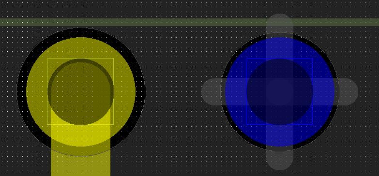
我的PCB上插装器件的孔和Shape的间距不一致,请看下图

灰色的Shape是GND,蓝色的孔是GND,采用十字连接,黄色的孔是普通网络。
黄色的孔和Shape的间距是10mil,这是在Constraints中设定的,正常。
蓝色的孔和Shape的间距只有5mil,和Constraints中的设置不一致,这是怎么回事呢?如何调整蓝色的孔和Shape的间距呢?
请各位指点。
谢谢

灰色的Shape是GND,蓝色的孔是GND,采用十字连接,黄色的孔是普通网络。
黄色的孔和Shape的间距是10mil,这是在Constraints中设定的,正常。
蓝色的孔和Shape的间距只有5mil,和Constraints中的设置不一致,这是怎么回事呢?如何调整蓝色的孔和Shape的间距呢?
请各位指点。
谢谢
有很多地方会影响到铜皮到孔的间距
1. 间距规则(Spacing Rule)中through pin to shape, hole to shape;还需要了解当前的net究竟应用的什么规则;
2. Same net Spacing Rule中through pin to shape, hole to shape;
3. 创建过孔焊盘是的选项enable antipads as route keepout;
4. via的property属性Dyn clearance overize;
5. shape的property属性Dyn clearance overize;
6. global dynamic shape parameters中的clearance overize;
可能还有。
你的问题可能是same net spacing rule中设置不正确。
SEEMS VERY GOOD!
问题已经解决,是same net spacing rule中设置不正确。
谢谢小编的指点。
