STM32_GPIO配置及库函数讲解——LED跑马灯
d as system clock source */
while(RCC_GetSYSCLKSource() != 0x08) {}
}
/* Enable GPIOC clock */
RCC_APB2PeriphClockCmd(RCC_APB2Periph_GPIOC, ENABLE);
}
/*******************************************************************************
* Function Name : NVIC_Configuration
* Description : Configures Vector Table base location.
* Input : None
* Return : None
*******************************************************************************/
void NVIC_Configuration(void)
{
#ifdef VECT_TAB_RAM
/* Set the Vector Table base location at 0x20000000 */
NVIC_SetVectorTable(NVIC_VectTab_RAM, 0x0);
#else /* VECT_TAB_FLASH */
/* Set the Vector Table base location at 0x08000000 */
NVIC_SetVectorTable(NVIC_VectTab_FLASH, 0x0);
#endif
}
/*******************************************************************************
* Function Name : GPIO_Configuration
* Description : Configures the different GPIO ports.
* Input : None
* Return : None
*******************************************************************************/
void GPIO_Configuration(void)
{
GPIO_InitTypeDef GPIO_InitStructure;
/* Configure PC.06, PC.07, PC.08 and PC.09 as Output push-pull */
GPIO_InitStructure.GPIO_Pin = GPIO_Pin_6 | GPIO_Pin_7 | GPIO_Pin_8 | GPIO_Pin_9;
GPIO_InitStructure.GPIO_Speed = GPIO_Speed_50MHz;
GPIO_InitStructure.GPIO_Mode = GPIO_Mode_Out_PP;
GPIO_Init(GPIOC, &GPIO_InitStructure);
}
/*******************************************************************************
* Function Name : Delay
* Description : Inserts a delay time.
* Input : nCount: specifies the delay time length.
* Return : None
*******************************************************************************/
void Delay(vu32 nCount)
{
for(; nCount != 0; nCount--);
}
#ifdef DEBUG
/*******************************************************************************
* Function Name : assert_failed
* Description : Reports the name of the source file and the source line number
* where the assert_param error has occurred.
* Input : - file: pointer to the source file name
* - line: assert_param error line source number
* Return : None
*******************************************************************************/
void assert_failed(u8* file, u32 line)
{
/* User can add his own implementation to report the file name and line number,
ex: printf("Wrong parameters value: file %s on line %d\r\n", file, line) */
/* Infinite loop */
while (1)
{
}
}
#endif
如何调试:在while(1)处设个断点。
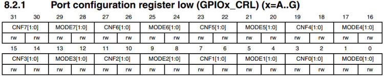
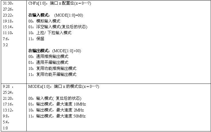
执行完GPIO_Configuration函数后,观察GPIO_CRL和GPIO_CRH寄存器,可以看到:
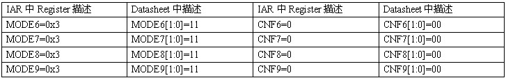
每个管脚模式配置由GPIO_CRL或GPIO_CRH中的4位决定,例如:PC6管脚由GPIO_CRL中的MODE6[1:0]和CNF6[1:0]这4位决定,其他的以此类推。
涉及到GPIO_CRL寄存器,如下所示
执行完GPIO_SetBits(GPIOC,GPIO_Pin_6); //点亮LED1,可以看到:GPIO_ODR的ODR6=1
执行完GPIO_ResetBits(GPIOC,GPIO_Pin_6); //熄灭LED1,可以看到:GPIO_ODR的ODR6=0
其他管脚如此类推。
STM32GPIO配置库函数LED跑马 相关文章:
- Windows CE 进程、线程和内存管理(11-09)
- RedHatLinux新手入门教程(5)(11-12)
- uClinux介绍(11-09)
- openwebmailV1.60安装教学(11-12)
- Linux嵌入式系统开发平台选型探讨(11-09)
- Windows CE 进程、线程和内存管理(二)(11-09)