PIC单片机 配置位如何写 (MPLAB X集成开发环境,XC编译器)
时间:11-13
来源:互联网
点击:
最近刚接触MPLABX集成开发环境,X16和X8编译器,和以前的PIC的开发环境有了很大的区别,这里就说一下新建工程的第一步,配置位的编写。#pragma config
For example:
// Brown-out Reset Enable bit: BOR disabled
// Data EEPROM Memory Code Protection bit: Data EEPROM code protection off
// In-Circuit Debugger Mode bit: In-Circuit Debugger disabled, RB6 and RB7 are general purpose I/O pins
// Flash Program Memory Write Enable bits: Write protection off; all program memory may be written to by EECON control
// Oscillator Selection bits: XT oscillator
// Watchdog Timer Enable bit: WDT disabled
// Flash Program Memory Code Protection bit: Code protection off
// Low-Voltage (Single-Supply) In-Circuit Serial Programming Enable bit: RB3 is digital I/O, HV on MCLR must be used for programming
// Power-up Timer Enable bit: PWRT disabled
#pragma config BOREN = OFF, CPD = OFF, DEBUG = OFF, WRT = OFF, FOSC = XT, WDTE = OFF, CP = OFF, LVP = OFF, PWRTE = OFF#pragma config
For example:
// Brown-out Reset Enable bit: BOR disabled
// Data EEPROM Memory Code Protection bit: Data EEPROM code protection off
// In-Circuit Debugger Mode bit: In-Circuit Debugger disabled, RB6 and RB7 are general purpose I/O pins
// Flash Program Memory Write Enable bits: Write protection off; all program memory may be written to by EECON control
// Oscillator Selection bits: XT oscillator
// Watchdog Timer Enable bit: WDT disabled
// Flash Program Memory Code Protection bit: Code protection off
// Low-Voltage (Single-Supply) In-Circuit Serial Programming Enable bit: RB3 is digital I/O, HV on MCLR must be used for programming
// Power-up Timer Enable bit: PWRT disabled
#pragma config BOREN = 0x0, CPD = 0x1, DEBUG = 0x1, WRT = 0x3, FOSC = 0x1, WDTE = 0x0, CP = 0x1, LVP = 0x0, PWRTE = 0x1#pragma config
For example:
// Brown-out Reset Enable bit: BOR disabled
// Data EEPROM Memory Code Protection bit: Data EEPROM code protection off
// In-Circuit Debugger Mode bit: In-Circuit Debugger disabled, RB6 and RB7 are general purpose I/O pins
// Flash Program Memory Write Enable bits: Write protection off; all program memory may be written to by EECON control
// Oscillator Selection bits: XT oscillator
// Watchdog Timer Enable bit: WDT disabled
// Flash Program Memory Code Protection bit: Code protection off
// Low-Voltage (Single-Supply) In-Circuit Serial Programming Enable bit: RB3 is digital I/O, HV on MCLR must be used for programming
// Power-up Timer Enable bit: PWRT disabled
#pragma config CONFIG = 0xFF39
For example:
// IDLOC @ 0x2000
#pragma config IDLOC0 = 0x3FFF
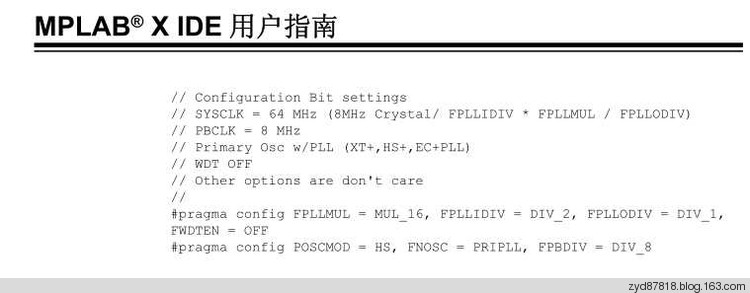
1:MPALB X IDE用户指南里面例子的配置位写法:
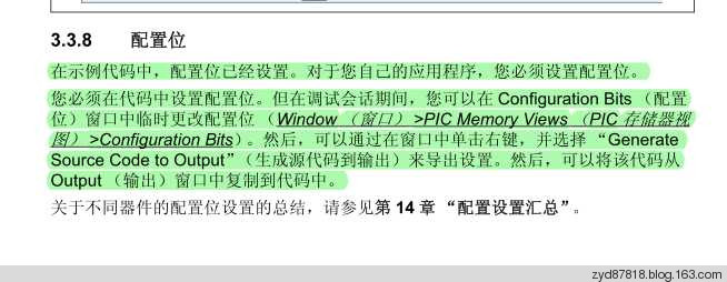
2:根据MPALB X IDE用户指南里面的描述,可以自动生成配置位的代码
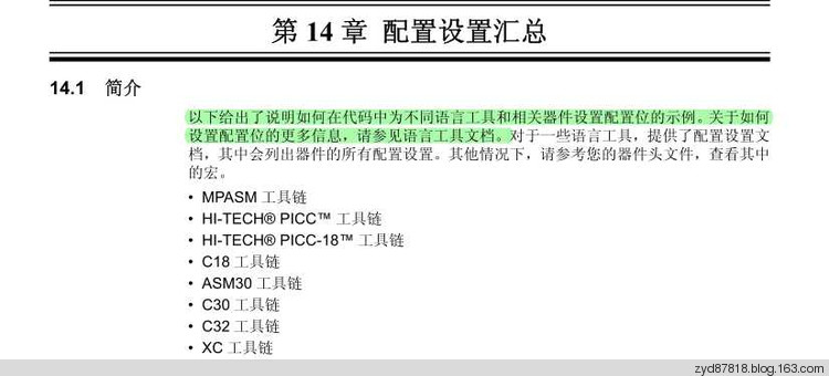
3:根据MPALB X IDE用户指南,说明配置位的编写是和编译器相关的,因此我们看编译器的说明文档
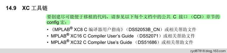
4:根据X8编译器的说明文档,看编译器安装目录下的文档说明
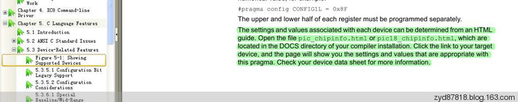
5:下面就是编译器安装目录下的文档说明
16F877A Support Information
#pragma config Usage
#pragma config =
For example:// Brown-out Reset Enable bit: BOR disabled
// Data EEPROM Memory Code Protection bit: Data EEPROM code protection off
// In-Circuit Debugger Mode bit: In-Circuit Debugger disabled, RB6 and RB7 are general purpose I/O pins
// Flash Program Memory Write Enable bits: Write protection off; all program memory may be written to by EECON control
// Oscillator Selection bits: XT oscillator
// Watchdog Timer Enable bit: WDT disabled
// Flash Program Memory Code Protection bit: Code protection off
// Low-Voltage (Single-Supply) In-Circuit Serial Programming Enable bit: RB3 is digital I/O, HV on MCLR must be used for programming
// Power-up Timer Enable bit: PWRT disabled
#pragma config BOREN = OFF, CPD = OFF, DEBUG = OFF, WRT = OFF, FOSC = XT, WDTE = OFF, CP = OFF, LVP = OFF, PWRTE = OFF
#pragma config =
For example:// Brown-out Reset Enable bit: BOR disabled
// Data EEPROM Memory Code Protection bit: Data EEPROM code protection off
// In-Circuit Debugger Mode bit: In-Circuit Debugger disabled, RB6 and RB7 are general purpose I/O pins
// Flash Program Memory Write Enable bits: Write protection off; all program memory may be written to by EECON control
// Oscillator Selection bits: XT oscillator
// Watchdog Timer Enable bit: WDT disabled
// Flash Program Memory Code Protection bit: Code protection off
// Low-Voltage (Single-Supply) In-Circuit Serial Programming Enable bit: RB3 is digital I/O, HV on MCLR must be used for programming
// Power-up Timer Enable bit: PWRT disabled
#pragma config BOREN = 0x0, CPD = 0x1, DEBUG = 0x1, WRT = 0x3, FOSC = 0x1, WDTE = 0x0, CP = 0x1, LVP = 0x0, PWRTE = 0x1
#pragma config =
For example:// Brown-out Reset Enable bit: BOR disabled
// Data EEPROM Memory Code Protection bit: Data EEPROM code protection off
// In-Circuit Debugger Mode bit: In-Circuit Debugger disabled, RB6 and RB7 are general purpose I/O pins
// Flash Program Memory Write Enable bits: Write protection off; all program memory may be written to by EECON control
// Oscillator Selection bits: XT oscillator
// Watchdog Timer Enable bit: WDT disabled
// Flash Program Memory Code Protection bit: Code protection off
// Low-Voltage (Single-Supply) In-Circuit Serial Programming Enable bit: RB3 is digital I/O, HV on MCLR must be used for programming
// Power-up Timer Enable bit: PWRT disabled
#pragma config CONFIG = 0xFF39
For example:
// IDLOC @ 0x2000
#pragma config IDLOC0 = 0x3FFF
#pragma config Settings
Register: CONFIG @ 0x2007
| BOREN = | Brown-out Reset Enable bit |
| OFF | BOR disabled |
| ON | BOR enabled |
| CPD = | Data EEPROM Memory Code Protection bit |
| OFF | Data EEPROM code protection off |
| ON | Data EEPROM code-protected |
| DEBUG = | In-Circuit Debugger Mode bit |
| OFF | In-Circuit Debugger disabled, RB6 and RB7 are general purpose I/O pins |
| ON | In-Circuit Debugger enabled, RB6 and RB7 are dedicated to the debugger |
| WRT = | Flash Program Memory Write Enable bits |
| OFF | Write protection off; all program memory may be written to by EECON control |
| HALF | 0000h to 0FFFh write-protected; 1000h to 1FFFh may be written to by EECON control |
| 1FOURTH | 0000h to 07FFh write-protected; 0800h to 1FFFh may be written to by EECON control |
| 256 | 0000h to 00FFh write-protected; 0100h to 1FFFh may be written to by EECON control |
PIC单片机配置 相关文章:
- Windows CE 进程、线程和内存管理(11-09)
- RedHatLinux新手入门教程(5)(11-12)
- uClinux介绍(11-09)
- openwebmailV1.60安装教学(11-12)
- Linux嵌入式系统开发平台选型探讨(11-09)
- Windows CE 进程、线程和内存管理(二)(11-09)