stm32 霍尔传感器接口
ary expects the Hall sensor signal
transitions to be in the sequence shown in Figure 30 for both 60° and 120° displaced Hall
sensors.
For these reasons, it is suggested to follow the instructions given below when connecting a
Hall-sensor equipped PM motor to your board:
1. Turn the rotor by hand in the direction assumed to be positive and look at the B-emf
induced on the three motor phases. For this purpose if the real neutral point is not
available, it can be reconstructed by means of three resistors for instance.
2. Connect the motor phases to the hardware respecting the positive sequence. Let
“Phase A”, “Phase B” and “Phase C” be the motor phases driven by TIM1_CH1,
TIM1_CH2 and TIM1_CH3, respectively (e.g. when using the MB459 board, a positive
sequence of the motor phases could be connected to J5 2,1 and 3).
3. Turn the rotor by hand in the direction assumed to be positive, look at the three Hall
sensor outputs (H1, H2 and H3) and connect them to the selected timer on channels 1,
2 and 3, respectively, making sure that the sequence shown in Figure 30 is respected.
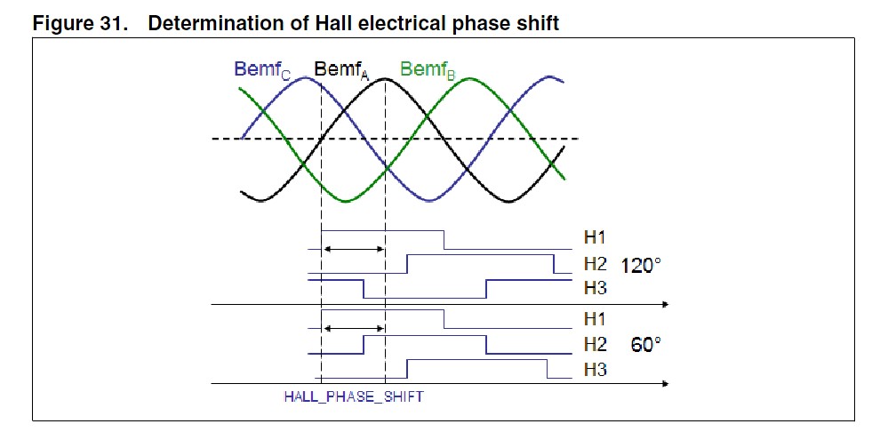
4. Measure the delay in electrical degrees betweenthe maximum of the B-emf induced on
Phase Aandthe first rising edge of signal H1. Enter it in the MC_hall_param.h header
file (HALL_PHASE_SHIFT). For your convenience, an example with
HALL_PHASE_SHIFT equal to –90 °C is illustrated in Figure 31.
stm32霍尔传感器接 相关文章:
- Windows CE 进程、线程和内存管理(11-09)
- RedHatLinux新手入门教程(5)(11-12)
- uClinux介绍(11-09)
- openwebmailV1.60安装教学(11-12)
- Linux嵌入式系统开发平台选型探讨(11-09)
- Windows CE 进程、线程和内存管理(二)(11-09)