stm32 霍尔传感器接口
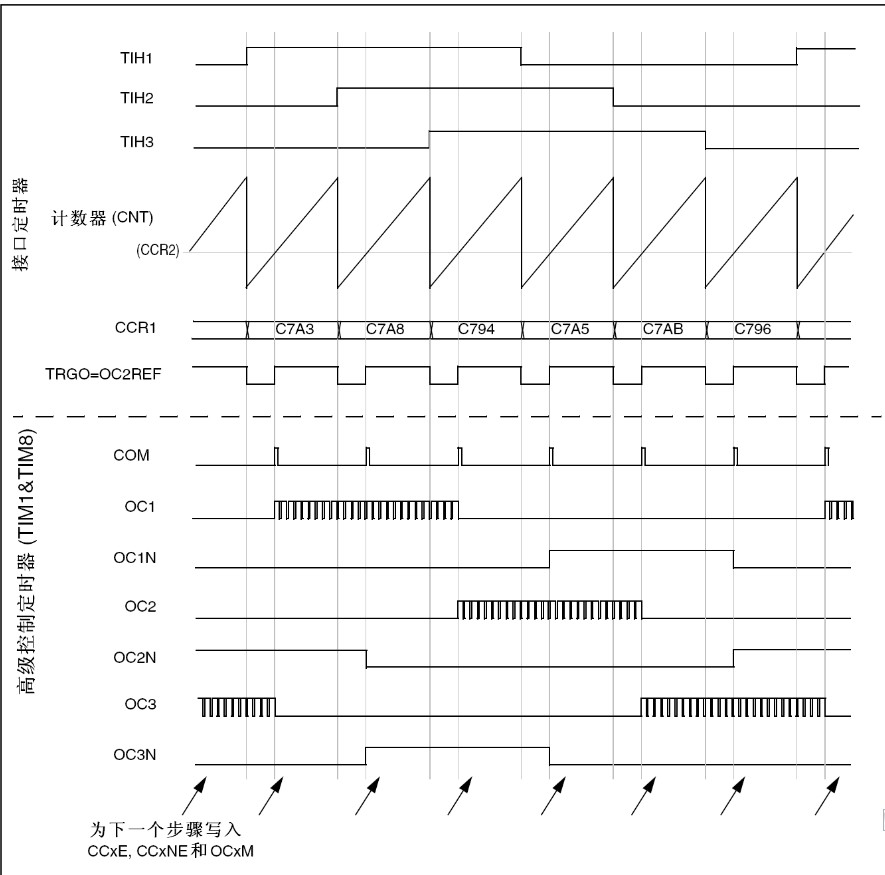
使用高级控制定时器(TIM1或TIM8)产生PWM信号驱动马达时,可以用另一个通用TIMx(TIM2、TIM3、TIM4或TIM5)定时器作为“接口定时器”来连接霍尔传感器,见图93,3个定时器输入脚(CC1、CC2、CC3)通过一个异或门连接到TI1输入通道(通过设置TIMx_CR2寄存器中的TI1S位来选择),“接口定时器”捕获这个信号。
从模式控制器被配置于复位模式,从输入是TI1F_ED。每当3个输入之一变化时,计数器从新从0开始计数。这样产生一个由霍尔输入端的任何变化而触发的时间基准。 “接口定时器”上的捕获/比较通道1配置为捕获模式,捕获信号为TRC(见图76)。捕获值反映了两个输入变化间的时间延迟,给出了马达速度的信息。 “接口定时器”可以用来在输出模式产生一个脉冲,这个脉冲可以(通过触发一个COM事件)用于改变高级定时器TIM1或TIM8各个通道的属性,而高级控制定时器产生PWM信号驱动马达。因此“接口定时器”通道必须编程为在一个指定的延时(输出比较或PWM模式)之后产生一个正脉冲,这个脉冲通过TRGO输出被送到高级控制定时器TIM1或TIM8。 举例:霍尔输入连接到TIMx定时器,要求每次任一霍尔输入上发生变化之后的一个指定的时刻,改变高级控制定时器TIMx的PWM配置。
● 置TIMx_CR2寄存器的TI1S位为’1’,配置三个定时器输入逻辑或到TI1输入,
● 时基编程:置TIMx_ARR为其最大值(计数器必须通过TI1的变化清零)。设置预分频器得到一个最大的计数器周期,它长于传感器上的两次变化的时间间隔。
● 设置通道1为捕获模式(选中TRC):置TIMx_CCMR1寄存器中CC1S=01,如果需要,还可以设置数字滤波器。
● 设置通道2为PWM2模式,并具有要求的延时:置TIMx_CCMR1寄存器中的OC2M=111和CC2S=00。
● 选择OC2REF作为TRGO上的触发输出:置TIMx_CR2寄存器中的MMS=101。 在高级控制寄存器TIM1中,正确的ITR输入必须是触发器输入,定时器被编程为产生PWM信号,捕获/比较控制信号为预装载的(TIMx_CR2寄存器中CCPC=1),同时触发输入控制COM事件(TIMx_CR2寄存器中CCUS=1)。在一次COM事件后,写入下一步的PWM控制位(CCxE、OCxM),这可以在处理OC2REF上升沿的中断子程序里实现。 下图显示了这个实例
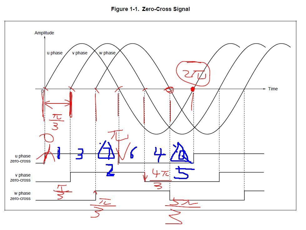
无刷电机每运行一圈,霍尔有六个状态,在每个状态均会进入一次中断,
正常运转的时候电机是按照1,3,2,6,4,5
http://www.ourdev.cn/bbs/bbs_content.jsp?bbs_sn=3764371&bbs_page_no=1&search_mode=1&search_text=hall&bbs_id=3020

Setting up the system when using Hall-effect sensors
Hall-effect sensors are devices capable of sensing the polarity of the rotor’s magnetic field;
they provide a logic output, which is 0 or 1 depending on the magnetic pole they face and
thus, on the rotor position.
Typically, in a three-phase PM motor three Hall-effect sensors are used to feed back the
rotor position information. They are usually mechanically displaced by either 120° or 60° and
the presented firmware library was designed to support both possibilities. To set up the
PMSM FOC software library for use with three Hall sensors, simply modify the
stm32f10x_MCconf.h and MC_hall_param.h header files according to the indications given
in Section 4.1 and Section 4.4, respectively.
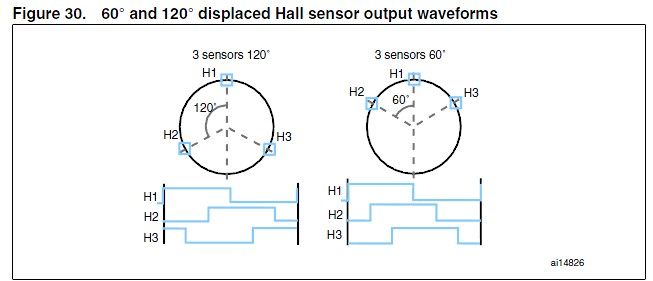
As shown in Figure 30, the typical waveforms can be visualized at the sensor outputs in
case of 60° and 120° displaced Hall sensors. More particularly, Figure 30 refers to an
electrical period (i.e. one mechanical revolution in case of one pole pair motor).
Figure 30. 60° and 120° displaced Hall sensor output waveforms
Since the rotor position information they provide is absolute, there is no need for any initial
rotor prepositioning. Particular attention must be paid, however, when connecting the
sensors to the proper microcontroller inputs.
In fact, as stated in Section 3.11, this software library assumes that the positive rolling
direction is the rolling direction of a machine that is fed with a three-phase system of positive
sequence. In that case to properly work, the software libr
stm32霍尔传感器接 相关文章:
- Windows CE 进程、线程和内存管理(11-09)
- RedHatLinux新手入门教程(5)(11-12)
- uClinux介绍(11-09)
- openwebmailV1.60安装教学(11-12)
- Linux嵌入式系统开发平台选型探讨(11-09)
- Windows CE 进程、线程和内存管理(二)(11-09)