一、
例程测试:
1. 编写includes.h文件
#ifndef __INCLUDES_H__
#define __INCLUDES_H__
//#include
//#include
//#include
//#include
//#include
#include
#include
#include "ucos_ii.h"
#include
#include
//#include
#endif
2. 编写Bsp.h和Bsp.c文件
Bsp.h文件,板级驱动文件。
#ifndef __BSP_H
#define __BSP_H
#define GPIO_PORT_LED GPIOF //根据自己板子情况修改
#define RCC_GPIO_PORT_LED RCC_APB2Periph_GPIOF //根据自己板子情况修改
#define GPIO_Pin_led1 GPIO_Pin_6 //根据自己板子情况修改
#define GPIO_Pin_led2 GPIO_Pin_7 //根据自己板子情况修改
#define LED1 0
#define LED2 1
void BSP_Init(void);
void led_on(uint32_t n);
void led_off(uint32_t n);
#endif
Bsp.c文件
#include
static void BSP_LED_Init(void);
// static void BSP_KEY_Init (void);
void BSP_Init (void)
{
SystemInit();
BSP_LED_Init();
// Init_Uart_on_Chip(9600);
// BSP_KEY_Init();
}
static void BSP_LED_Init(void)
{
GPIO_InitTypeDef GPIO_InitStructure;
RCC_APB2PeriphClockCmd(RCC_GPIO_PORT_LED, ENABLE) ; //使能时钟 //根据自己板子情况修改
GPIO_InitStructure.GPIO_Pin = GPIO_Pin_led1|GPIO_Pin_led2; //根据自己板子情况修改
GPIO_InitStructure.GPIO_Mode = GPIO_Mode_Out_PP;
GPIO_InitStructure.GPIO_Speed = GPIO_Speed_2MHz;
GPIO_Init(GPIO_PORT_LED, &GPIO_InitStructure); //根据自己板子情况修改
}
void led_on(uint32_t n)
{
switch (n)
{
case LED1: GPIO_SetBits(GPIO_PORT_LED, GPIO_Pin_led1);
break;
case LED2: GPIO_SetBits(GPIO_PORT_LED, GPIO_Pin_led2);
break;
default:
break;
}
}
void led_off(uint32_t n)
{
switch (n)
{
case LED1: GPIO_ResetBits(GPIO_PORT_LED, GPIO_Pin_led1); break;
case LED2: GPIO_ResetBits(GPIO_PORT_LED, GPIO_Pin_led2); break;
default: break;
}
}
3. 编写app_cfg.h和app.c文件
app_cfg.h
#define STARTUP_TASK_PRIO 4
#define LED1_TASK_PRIO 6
#define STARTUP_TASK_STK_SIZE 80
#define LED1_TASK_STK_SIZE 80
app.c文件
#include
static OS_STK startup_task_stk[STARTUP_TASK_STK_SIZE]; //开开辟任务堆栈
static OS_STK led1_task_stk[LED1_TASK_STK_SIZE ]; //开辟任务堆栈
static void systick_init(void); //函数声明
static void systick_init(void)
{
RCC_ClocksTypeDef rcc_clocks;
RCC_GetClocksFreq(&rcc_clocks); //调用标准库函数,获获取系统时钟。
SysTick_Config(rcc_clocks.HCLK_Frequency / OS_TICKS_PER_SEC); //初始化并使能 SysTick
//OS_TICKS_PPER_SEC 是在 os_cfg.h 中定义的
}
static void led1_task (void *p_arg)
{
p_arg=p_arg; //防止编译器产生警告
while(1)
{
led_on(LED1);
OSTimeDlyHMSM(0,0,1,0); //1s 延时,释放 CPU 控制权
led_off(LED1);
OSTimeDlyHMSM(0,0,1,0); //1s 延时,释放 CPU 控制权
}
}
static void startup_task(void *p_arg)
{
systick_init();
OSTaskCreate(led1_task, 0,
&led1_task_stk[LED1_TASK_STK_SIZE - 1],
LED1_TASK_PRIO);
while(1)
{
led_on(LED2);
OSTimeDlyHMSM(0,0,0,500); //500ms 延时,释放 CPU 控制权
led_off(LED2);
OSTimeDlyHMSM(0,0,0, 500); //500ms 延时,释放 CPU 控制权
}
}
int main(void)
{
BSP_Init();
OSInit();
// g_TxMbox=OSMboxCreate((void*)0); //创建全局信号-消息邮箱
OSTaskCreate(startup_task, (void *)0,
&startup_task_stk[STARTUP_TASK_STK_SIZE - 1],
STARTUP_TASK_PRIO);
OSStart();
return 0;
}
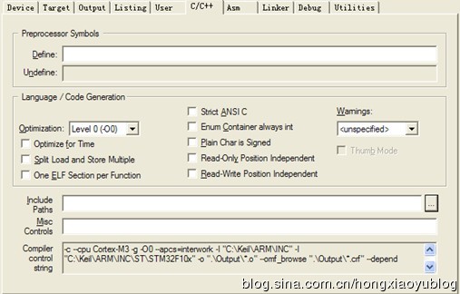
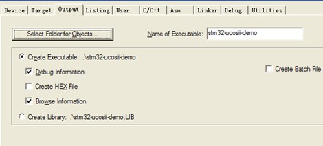
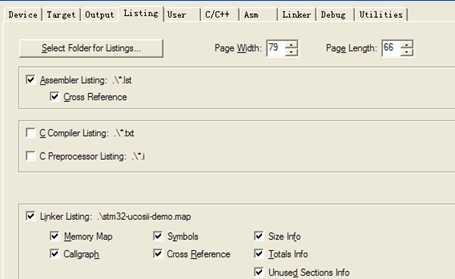
最后再设置 keil选项卡:
a) 设置工程输出路径到 ProjectOutput 下;
b) 设置工程 Listing 路径到ProjectList 下;
c) 设置头文件包含路径: