这里就涵盖了STM32的IO控制了,按键是输入,蜂鸣器与LED控制是输出。
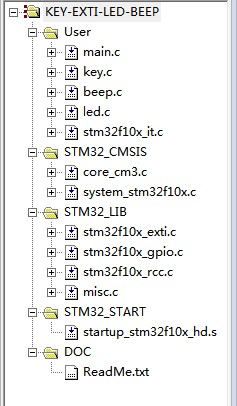
首先来一张工程的结构图:
代码解说就不用了吧,IO口这玩意也没有什么好说的。直接上代码:
首先是main.c部分
#include"stm32f10x.h"
#include"key.h"
#include"beep.h"
#include"led.h"
KeyNumber Key_Number=KeyNone;
int main(void)
{
Led_Init(); //LED初始化
Beep_Init(); //蜂鸣器初始化
Key_Init();
#ifdef Key_Polling //采用查询的方式
//Key_Init(); //按键GPIO初始化
while(1)
{
switch(Get_Key_Number())
{
case Key1:
Led_Spark(Led1,1,LedOn);
Beep_State(1,BeepOn);
break;
case Key2:
Led_Spark(Led2,1,LedOn);
Beep_State(1,BeepOn);
break;
case Key3:
Led_Spark(Led3,1,LedOn);
Beep_State(1,BeepOn);
break;
case Key4:
Led_Spark(Led4,1,LedOn);
Beep_State(1,BeepOn);
break;
default:
LedAll_Off;
Beep_Off;
break;
}
}
#endif
#ifdef Key_Interrupt //采用中断的方式
//Key_Init();
Key_EXTI();
Key_NVIC();
while(1)
{
#if 0 //这部分现在这里导致按键时好时坏 原因不明
switch(Key_Number)
{
case Key1:
Led_Spark(Led1,1,LedOn);
Beep_State(1,BeepOn);
Key_Number=KeyNone;
break;
case Key2:
Led_Spark(Led2,1,LedOn);
Beep_State(1,BeepOn);
Key_Number=KeyNone;
break;
case Key3:
Led_Spark(Led3,1,LedOn);
Beep_State(1,BeepOn);
Key_Number=KeyNone;
break;
case Key4:
Led_Spark(Led4,1,LedOn);
Beep_State(1,BeepOn);
Key_Number=KeyNone;
break;
default:
LedAll_Off;
Beep_Off;
Key_Number=KeyNone;
break;
}
#endif
}
#endif
}
2.接下载是按键key.c 与key.h
#include"stm32f10x.h"
#include"key.h"
#ifdef Key_Polling
static void Delay(vu32 Time)
{
for(;Time!=0;Time--);
}
void Key_Init(void)
{
GPIO_InitTypeDef GPIO_InitStructure;
RCC_APB2PeriphClockCmd(Key1_RCC,ENABLE);
GPIO_InitStructure.GPIO_Pin=Key1_Pin;
GPIO_InitStructure.GPIO_Mode=GPIO_Mode_IPU;
GPIO_Init(Key1_Port,&GPIO_InitStructure);
RCC_APB2PeriphClockCmd(Key2_RCC,ENABLE);
GPIO_InitStructure.GPIO_Pin=Key2_Pin;
GPIO_Init(Key2_Port,&GPIO_InitStructure);
RCC_APB2PeriphClockCmd(Key3_RCC,ENABLE);
GPIO_InitStructure.GPIO_Pin=Key3_Pin;
GPIO_Init(Key3_Port,&GPIO_InitStructure);
RCC_APB2PeriphClockCmd(Key4_RCC,ENABLE);
GPIO_InitStructure.GPIO_Pin=Key4_Pin;
GPIO_Init(Key4_Port,&GPIO_InitStructure);
}
KeyNumber Get_Key_Number(void)
{
KeyNumber Key_Number;
Key_Number=KeyNone;
if(!GPIO_ReadInputDataBit(Key1_Port,Key1_Pin))
{
Delay(0xffff);//延时防抖
if(!GPIO_ReadInputDataBit(Key1_Port,Key1_Pin))
Key_Number=Key1;
}
if(!GPIO_ReadInputDataBit(Key2_Port,Key2_Pin))
{
Delay(0xffff);
if(!GPIO_ReadInputDataBit(Key2_Port,Key2_Pin))
Key_Number=Key2;
}
if(!GPIO_ReadInputDataBit(Key3_Port,Key3_Pin))
{
Delay(0xffff);
if(!GPIO_ReadInputDataBit(Key3_Port,Key3_Pin))
Key_Number=Key3;
}
if(!GPIO_ReadInputDataBit(Key4_Port,Key4_Pin))
{
Delay(0xffff);
if(!GPIO_ReadInputDataBit(Key4_Port,Key4_Pin))
Key_Number=Key4;
}
return Key_Number;
}
#endif
#ifdef Key_Interrupt
void Key_Init(void)
{
GPIO_InitTypeDef GPIO_InitStructure;
RCC_APB2PeriphClockCmd(RCC_APB2Periph_AFIO,ENABLE);
RCC_APB2PeriphClockCmd(Key1_RCC,ENABLE);
GPIO_InitStructure.GPIO_Pin=Key1_Pin;
GPIO_InitStructure.GPIO_Mode=GPIO_Mode_IPD;
GPIO_Init(Key1_Port,&GPIO_InitStructure);
RCC_APB2PeriphClockCmd(Key2_RCC,ENABLE);
GPIO_InitStructure.GPIO_Pin=Key2_Pin;
GPIO_Init(Key2_Port,&GPIO_InitStructure);
RCC_APB2PeriphClockCmd(Key3_RCC,ENABLE);
GPIO_InitStructure.GPIO_Pin=Key3_Pin;
GPIO_Init(Key3_Port,&GPIO_InitStructure);
RCC_APB2PeriphClockCmd(Key4_RCC,ENABLE);
GPIO_InitStructure.GPIO_Pin=Key4_Pin;
GPIO_Init(Key4_Port,&GPIO_InitStructure);
}
void Key_EXTI(void)
{
EXTI_InitTypeDef EXTI_InitStructure;
GPIO_EXTILineConfig(Key1_EXTI_PortSource,Key1_EXTI_PinSource); //配置GPIO为外部中断事件
EXTI_InitStructure.EXTI_Line =Key1_EXTI_Line; //中断线
EXTI_InitStructure.EXTI_Mode =EXTI_Mode_Interrupt; //中断方式
EXTI_InitStructure.EXTI_Trigger =EXTI_Trigger_Falling; //下降沿
EXTI_InitStructure.EXTI_LineCmd =ENABLE; //使能中断线